Article
Meanwhile, back at ThreadWarp: Further Exploration of a SolidWorks Master Model

June 1, 2026 ...

Welcome back to our follow-up to Part 1 of the imaginary, but conceivable, “ThreadWarp” project from Fresh Consulting. This installment references files from the following downloadable Pack and Go zip archive: 01025-800-0005653 – THREAD WARP TOP LEVEL ASSEMBLY_REV02V19.zip
Last time I pretended to be an industrial designer—let’s call him “ID-me”—working on ThreadWarp, a bedside and bed top media streaming and sleep enhancement device. ID-me iterated and then, by post’s end, delivered an ID form model, ThreadWarp_Form0.7.SLDPRT.
The model is a reference file for the mechanical engineer, “ME-me”, to start from. We call this file an “ID Release” or “North Star” Revision.
While ID-me delivered a multi-bodied single part file, it could have been an assembly file with a mix of external and virtual parts.
Ideally, ID-me would have built quick physical form studies (small-scale or full-scale 3D prints) to validate proportions, aesthetics, and ergonomics. Their CAD file is simple from a feature tree and organizational perspective. For the client’s and my sake, it was done efficiently, without fine detail. Since I’m only getting started, it’s reasonable for me to rebuild the geometry from scratch (into master model 1). Industrial designers, no matter their experience, do us no favors by diving in too deep when detailing their form studies. Especially if an engineer is going to rebuild from scratch anyway. Fresh’s ID team members are skilled SolidWorks users. Over the years, I find that I do less and less ‘build from scratch’ when creating the ID master model (MM1).
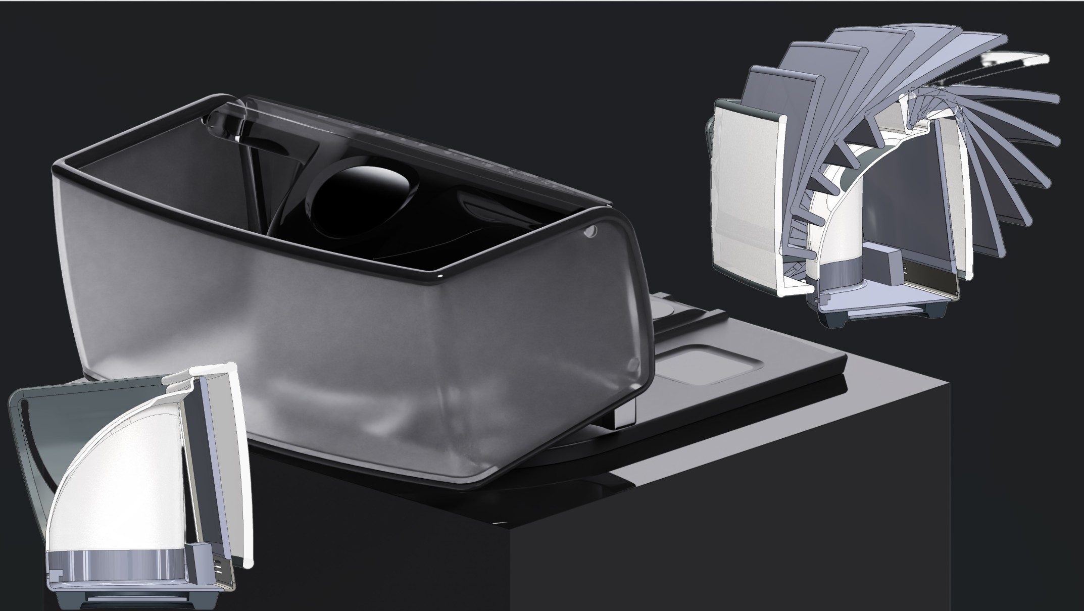
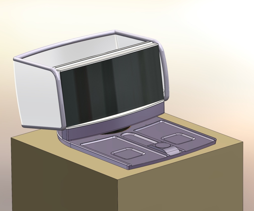
Here are KeyShot renders from the last post. All the geometry came from the original native SolidWorks ‘ThreadWarp_Form0.7.SLDPRT’ file. These renderings (and not the native SolidWorks CAD renders) only begin to communicate the design intent of a glowing enclosure that acts like an ambiance light that can be used in dark environments to simulate sunrise in the morning and sunset before retiring for the night.


I notice now that the image of the hood above implies translucence: you can see through it to the front bezel and side of the enclosure. That’s a mistake: ID-me hopes that the hood, based on Boeing’s 787 Dreamliner liquid crystal window shade technology, will be entirely opaque, blocking all light emitted by the display when articulated to this position.
As ME-me, I’ve only been cursorily involved so far. For practical reasons, strategy and ID teams will have carried out the bulk of the work up to this point. The architecture – how the parts of the product are divided up (aka “parts breakout”), what materials they’re made of, how they’re manufactured and assembled is still ambiguous. As I roll through ID-me’s feature tree, I see how the forms were built. But instead of focusing on CAD details and diving into the MM1 rebuild, I consider project requirements at a high level:
- Where are the biggest design/engineering/manufacturing risks?
- What features, areas, and components need fleshing out?
- How might they change over the course of the project and
- How might a change in one area or revised hardware selection impact features or other parts of the product?
- What architectures are most conducive to the client’s aesthetic and cost goals?
I take a beat trying to consider all aspects of the design before launching SolidWorks. A thoughtful pause at the outset could save our team significant time and challenge down the road. I think about the product (features, performance, requirements) and finally begin to think about how to build it in CAD:
- What information should I build into the master model(s)?
- How and when should I add the information?
- Should I put it in
- MM1, my ID capture,
- MM2, the architecture,
- Or save it for the detailed design of each part after I’ve created a top-level assembly (TLA)?
I need to remind myself that master models are living documents. I can add sketches and bodies later, well after I’ve broken the design out to individual part files inserted in the TLA. I dive deeper into the project and the details of the product.
ThreadWarp features, performance, and requirements
I imagine ThreadWarp’s intended use cases:
- It’s a bedside ambient light device and smart alarm clock,
- with inductive charging pads for a phone or two, ear buds, and a smart watch.
- It enables a restless or insomniac user to consume digital content without waking or bothering their partner.
- Additionally, the same couple might choose to view content together.
- The client has mentioned that they’d like it to be a listening device, recording the user while they sleep to help diagnose sleep apnea.
- The client wants the device to be voice and touch-controllable.
ThreadWarp is really two enclosures that interact with each other: A Display unit and a Charging Pad
The Display Unit (1.0) houses:
- One TBD 10 to 14-inch diagonal, presumably OLED display
- An ambient light sensing (ALS) photodiode or phototransistor system – presumably needed for subtle light brightness adjustments
- One articulating, electrically connected, and adjustable opacity light diffusing to fully light-blocking hood
- Preferably two TBD stereo speakers
- One or two microphones—one facing the user and, if needed, one to listen to the ambient/background
- Enough likely surface mount RGB LEDs to evenly illuminate the translucent upper case housing of the unit
- At least one circuit board including wifi and Bluetooth-capable antenna(ae)
- One USB-C connector for direct charging/powering of the unit
- One TBD presumably CapSense touch circuit with at least one “button” zone mounted at the top of the top case for unit control functions
- Perhaps an affordance for haptic feedback – especially appropriate if the “button” zone is non-moving, non-tactile Cap Sense-based
- One inductive charging receiving coil in the base foot of the unit
- A TBD onboard rechargeable battery
The Charging Pad (2.0) houses:
- Two TBD inductive charging coils, presumably capable of charging both phones (Android and IOS universal?) and ear buds (in their storage cases – Android and IOS universal?).
- One TBD Display unit charging coil (perhaps identical to the phone/bud coils above)
- One TBD smart watch charging coil (Android and IOS universal?)
- Three discrete RGB LED charge status indicators (likely surface mount, with a light pipe for each) and an RGB LED Display Unit base charge status “light ring” (around the Display Unit base recess)
- At least one circuit board
- One USB-C charging connector to power the inductive charging recesses
The two units interface with each other loosely: the user places the Display Unit on the Charging Pad in a base recess without any locking or registration mechanisms. Above and beyond mechanical stability and functionality, we’re concerned with charging performance, which will be affected by the mechanical registration of the enclosures and charging coils (think proximity and alignment of receiver to transmitter coils). Other than these considerations, the Charging Pad and Display Unit are independent of each other.
Some preliminary Display Unit feature and performance requirements, as worked out with the client, follow:
1.1.1 The Display Unit is ergonomically friendly and light enough to be easily grabbed and positioned single-handed.
1.1.2 It should be stable and rotatable (swivel) relative to the Charging Pad, while nested in it,
1.1.3 It is easily removable (without mechanical release mechanisms) from the Charging Pad.
1.2.1 The Display Module is a 16:9 aspect ratio (Client will consider other aspect ratios, e.g., 2.35:1 – anamorphic widescreen or 1.85:1 – flat widescreen if there is a compelling reason or if a different aspect ratio suggests a better alternative to letter boxing or to deal with vertical, aka portrait formats)
1.2.2 Display Module has an active area with 10 to 14 inch diagonal,
1.2.3 Display Module screen surface has 50 to 80 inch cylindrical convex radius of curvature
1.2.4 Display Module has brightness and contrast performance comparable to the best high-performance mobile phone OLED and AMOLED displays (full-screen sustained brightness of 200 – 450 nits with ambient contrast ratio, ACR, up to infinite).
1.3.1 Display Unit shall measure ambient light.
1.3.2 Ambient light sensor should be shielded from direct light from the emission portions of the display module and display unit.
1.3.3 Display module to have automatic brightness adjustment with intuitive user override capability
1.4.1 The Light Hood (Hood) should be permanently affixed to the Display Unit.

1.4.2 It should be continuously adjustable from (a) fully closed, through fully (b) deployed, and (c) fully flipped back, operating with enough friction in its tracks to stay wherever it is left positioned, preferably without the use of a user-engaged clutch or locking mechanism.
1.4.3 Hood opacity should operate from (i) evenly distributed light transmission through (ii) 100% opaque. While continuous or stepped increments are interesting to the client, only the two light transmission endpoints are required.
1.4.4 The Hood must be switchable from (i) translucent to (ii) opaque in any position and maintain its state as it is adjusted continuously from 1.4.2a to 1.4.2b and back or from 1.4.2b to 1.4.2c and back… But the client also acknowledges that perhaps the hood could have specific opacity/translucence settings in specific orientations (timing)—i.e., whenever the hood is in deployed blinder positions, it would be fully opaque.
1.5.1 Display Unit shall have an array of LED lights capable of simulating the setting and rising sun
1.5.2 User shall be able to set the brightness of LED array output using an app on their phone or on the Display Module screen (implies touch screen)
1.5.3 User shall be able to adjust the LED array light output color and temperature using an app on their phone or on the Display Module screen
1.6.1 Minimum acceptable audio performance should be comparable to Amazon Echo / Dot fidelity, including bass performance
1.7.1 System should be capable of receiving voice commands even while playing audio
1.7.2 System should be able to listen to and record users while they sleep for sleep apnea analysis and quality assessments
…and so on.
As you can imagine, the list of requirements, with or without consideration of cost and practicality, can be ambiguous, poorly quantized, unwieldy or, especially at the outset of a project, incomplete. As the lead ME, I consider what requirements impact our work, workflow, and how we might need to pivot if they change midstream. The Display Unit, is a complex mechanical design. I can imagine many dependencies associated with the various components.
Here are my top 5 design concerns as they relate to project risk (ranked from highest to lowest):
- Complexity of Hood articulation with its required electrical interconnections and (mechanical) timing awareness
- Complexity of Hood LCD technology – the relationships of geometry, parts finish, and assembly to resulting optical performance
- Display Module shape/size and its impact on overall ID form, size, weight, and ergonomics
- Audio speaker placement, orientation, and size (including cabinet volume, design constraints, and potential vent requirements)
- LED Array/Case part geometry, thickness, material, surface finish/texture implementation, and internal components placement all affect smooth/even gradient light transmission
It will be important to work closely with the EE team and develop quick proof-of-concept models to validate initial favored design approaches. All five, plus the basics of architecture (parts breakout), anticipated project development, and assembly, should be considered when deciding what to include in the master model.
The Charging Pad feels low risk. My only concern is with universal charging compatibility:
- Is it possible to provide a single solution that can charge for complete ranges of qi charging phones, watches, and earbud cases?
- in both IOS and Android operating systems?
With these product/project concerns in mind, and with master modeling goals of:
- Maximizing flexibility and speed to adapt to downstream changes, revisions, and feature redefinition
- Minimizing or eliminating external referencing in CAD (to reduce load time, modeling time, and SolidWorks crashes) and
- Reducing the risk of missing downstream changes (through poor communication or not properly capturing relationships between parts) that impact multiple dependent parts
I devise our master model strategy.
As this is a consumer product, with complex forms, many ergonomic and feature challenges, and dependence on untried unsourced technology, I decide to capture only the ID in our first master model, MM1, which I’ll pull (using the insert part command) into master model 2 (MM2) as its first feature. I’ll make MM2 as sparse and simple as possible, focusing on internal components layout, fastening, and interface relationships between parts. If I were working alone, I’d do up to 2⁄3 ‘s of my design work, including detailing entirely in master model 1 and master model 2 files, waiting until the design and architecture were stable before creating a top-level assembly (TLA). Since I have team mates and the charging pad, hood, and display unit enclosure parts can be developed in parallel, I opt to create a TLA as soon as possible. I hope to get team mates started on hood & top case light emission and articulation proof of concept derisking. We can also start Charging Pad detailed housing parts design once electrical to mechanical layouts and coil choices are solidified.
Dive into the CAD: Building MM1 (Master Model 1)
I attempt to capture basic meaningful geometry and functional volumes of the significant internal components of the product. I do not detail any of the internal components unless they somehow impact the ID or take up a large amount of internal space. The ID vision is derived from the underlying dimensions of the display module, in particular. So I work to build easily adjusted display geometry as the first features and then reference that module body, its faces, edges, and datums for subsequent features. I dimension/reference other component geometry and placements from a minimum of display module edges, points, faces, and planes, (rather than the part origin). If a component doesn’t significantly impact details of the ID form, then I don’t need to put it in MM1. The dimensioning and definition are informed by how components shape, and placements might change as they’re selected, positioned, or fastened. I’m working to faithfully re-create ID-me’s form vision while following internal components placement and envelopes.
As I flesh out the ID, I try to anticipate architecture, material selections, and parts manufacturing process design constraints—e.g. lines of draw, draft, and nominal wall thickness(es) for molded parts, etc.. When I finish MM1, I run it past the industrial designer. We talk through any reasons for departing from their original design, sharing concerns and proposing solutions.
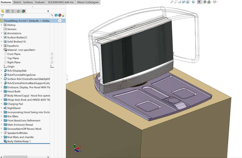
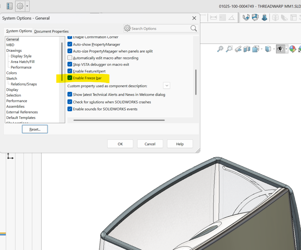
I came up with this part file, MM1 for ThreadWarp: → “01025-100-0004749 – THREADWARP MM1REV02V19.SLDPRT”

Note the yellow bar at the bottom of the feature tree which “freezes” all features to save on rebuild and load times (because the file won’t need to be rebuilt when you next load it). I recommend you try feature freezing on your next more complex slow-loading projects (rebuilds won’t include any features above the yellow line). You enable it from “System Options/General”:
Let’s roll up through the MM1 model and see how it’s built:
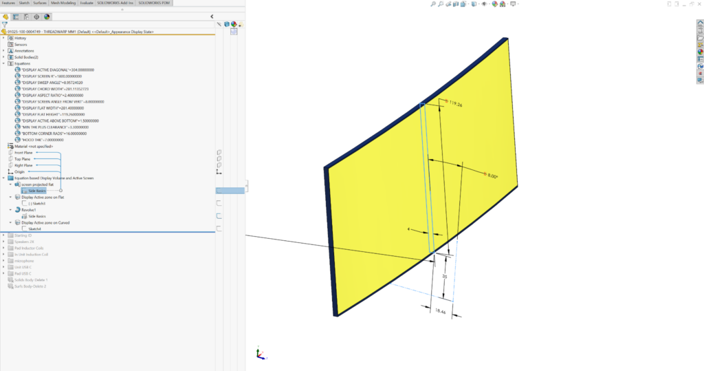
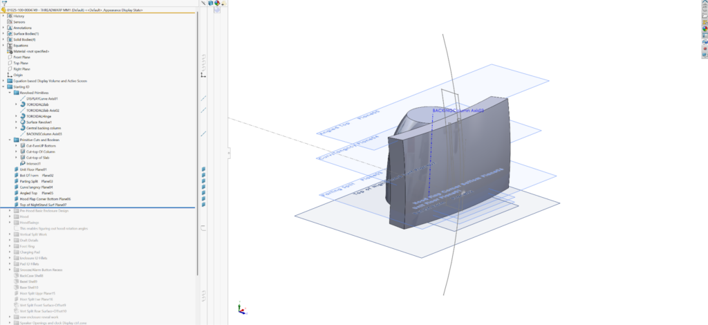
All of the form should follow the display module, so that’s where I started (see the “Equations” and “Equation-based Display Volume and Active Screen” folders at the top of the MM1 feature tree):
I used global (dimension) variables to make relevant display module dimensions easy to find and adjust. Dimension values shown with red “Σ’s” indicate the use of equations or other reference dimensions inside the sketch. In this example, they’re also global variables I can set and tweak by “managing equations” in the Equations folder. “DISPLAY SCREEN R”, “DISPLAY FLAT HEIGHT”, “DISPLAY SCREEN ANGLE FROM VERT” are all called by the first feature. I’ve made overall outside dimensions of the display and the active screen area (shown in yellow below) global variables as well.
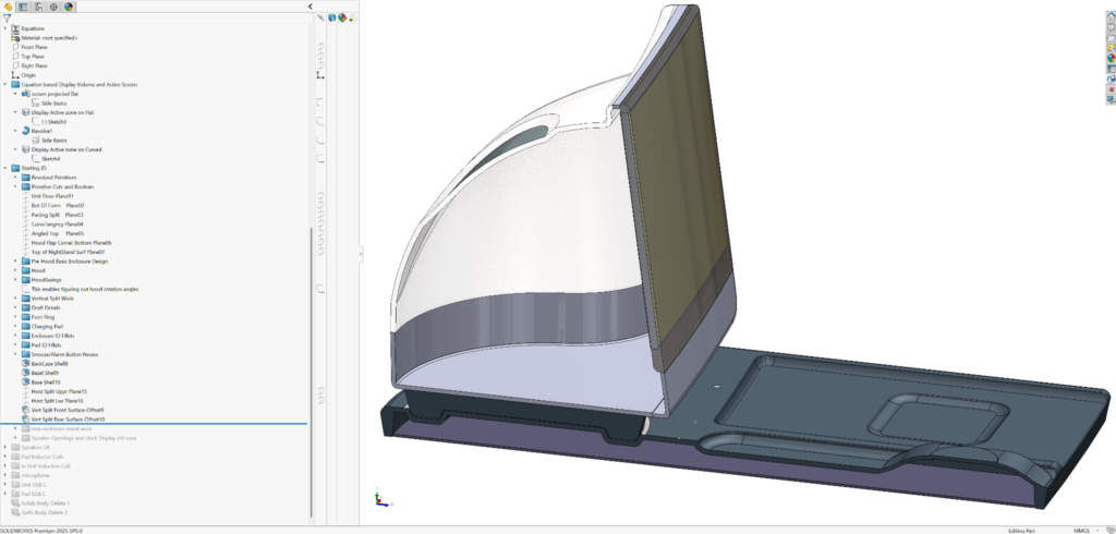
The majority of the ID master model definition happens in the “Starting ID” folder.
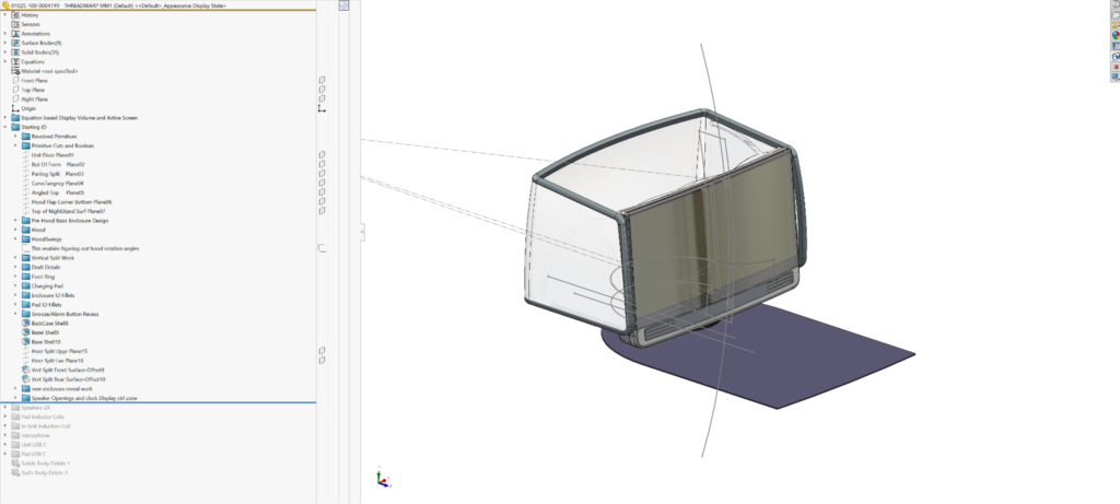
First I build some basic (volumetric) primitives that reference the display module body:
Then I work those primitive forms into practical, viable enclosure and screen part volumes.
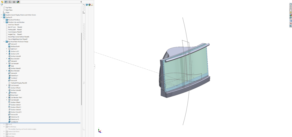
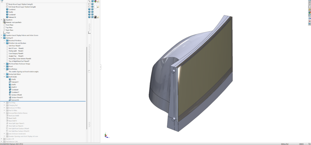
Then I develop the hood, referencing the enclosure and display bodies. I put this work in the “Hood” folder:
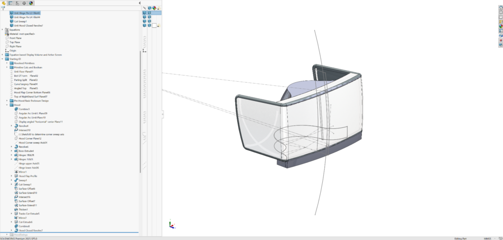
With the hood defined, I work on its articulation in the “HoodSwings” folder. I haven’t figured out how to do advanced cam/edge following mates in a multi-bodied part file (as opposed to an assembly). So I used the move/copy body feature instead:
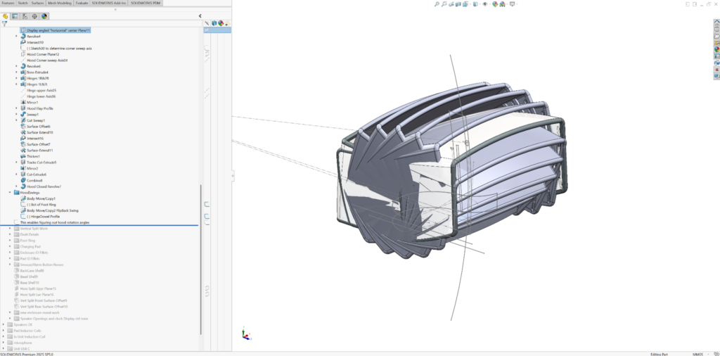
In anticipation of front the unit parts breakout, I split the slab front of the enclosure into meaningful part sub-part volumes (see “Vertical Split Work” folder):

When I’m confident that I know the lines of draw for each part, I build draft into them. I don’t worry about getting the actual angle right (see “Draft Details” folder); I take my best guess. It makes sense to build these considerations in. They’ll impact the overall form and the mechanical interfaces between parts. All of the bodies are dead solid for now. They’re coming up in parallel and share references where they meet up
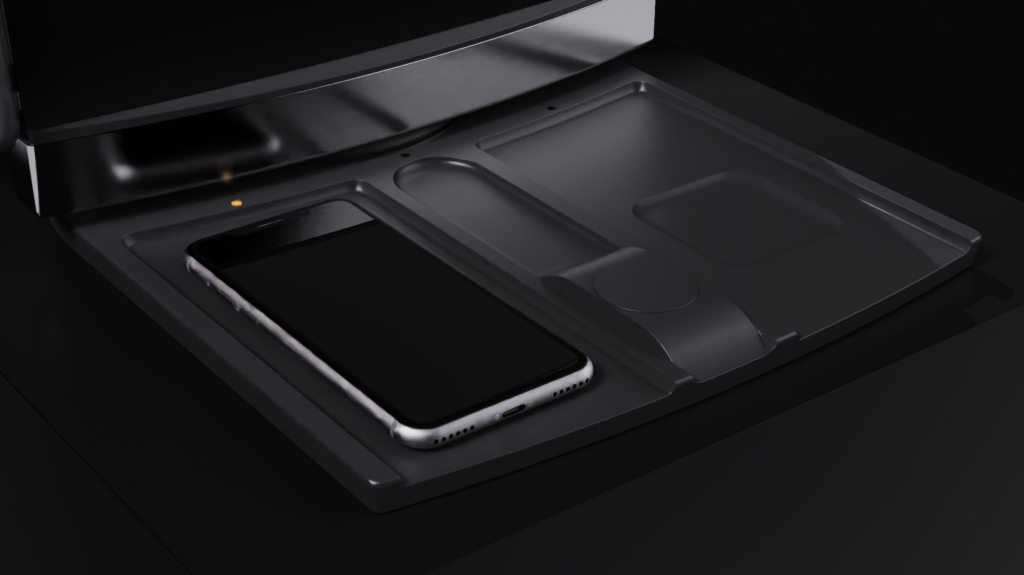
I add the Foot ring and qi charging base form (see the “Foot Ring” folder):
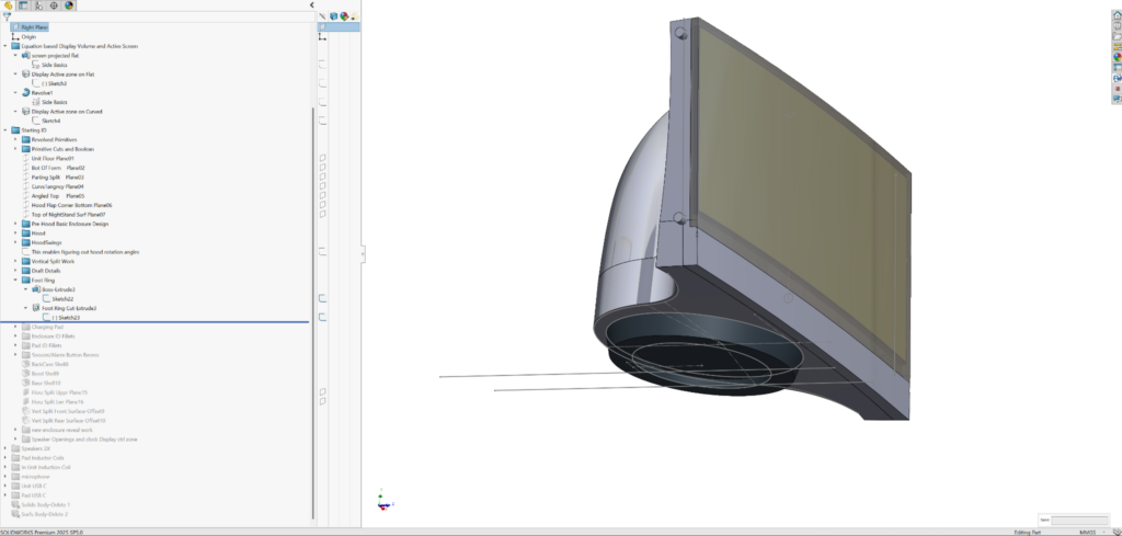
I work up the Charge Pad as its own enclosure, but follow the ring foot pad of the display unit, which nests in it:
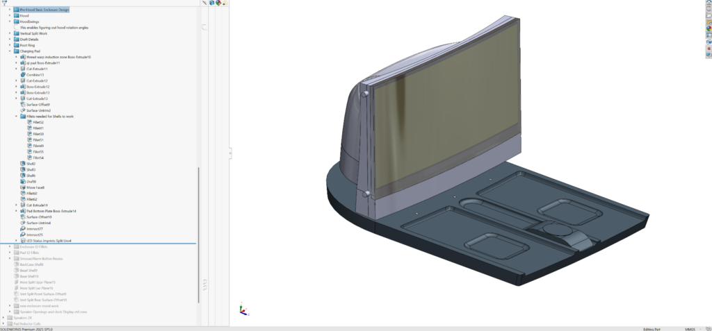
Then I add fillets to the display unit and charging pad (see the “Enclosure ID Fillets” and “Pad ID Fillets” folders) . While I generally like to save fillets for close to last, in this case, I need to put them in to prepare for the shell commands that follow.

I add the remaining fine outside-of-the-enclosure detail, in this case, the recess for snooze bar (see “Snooze/Alarm Button Recess” folder) before shelling.
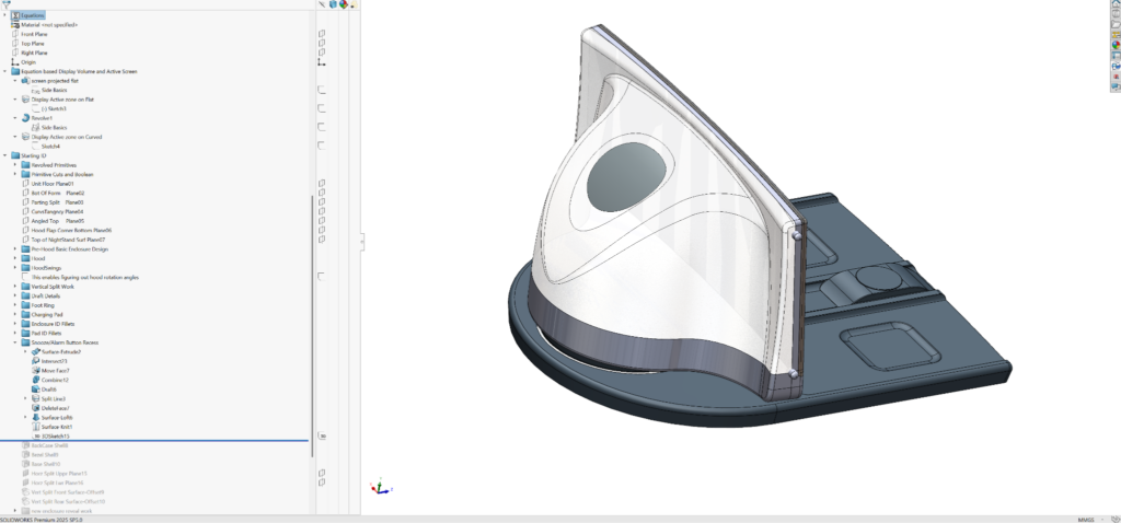
Now I shell the enclosure parts. I’m showing a section view below for you to see the result of shelling, not because the features are cut in half (while the design is symmetric, I’ve learned that with lofts and many other SolidWorks features, mirroring and the ripples you may want to follow them are not robust):
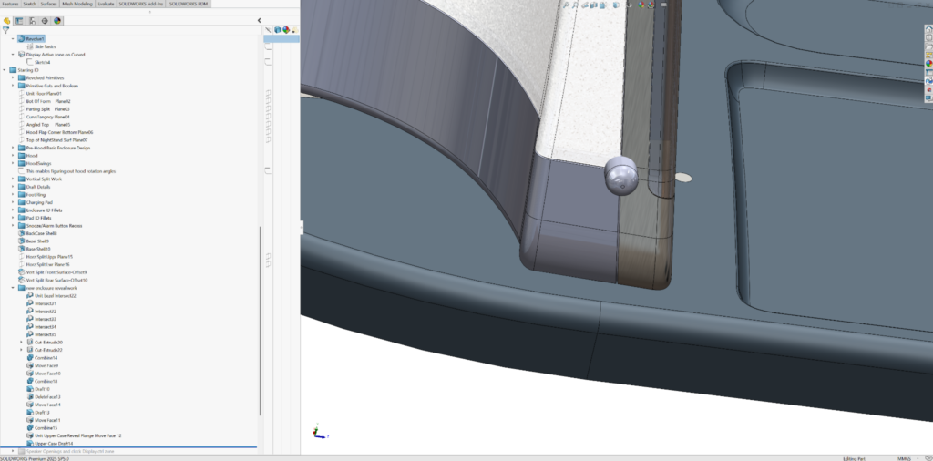
Then I implement the fine interface details between enclosure parts. These details are part of the ID and often come down to part reveals (aka design gaps or split) work. The reveals in this master model are separate bodies and are only accurate as seen from the outside of the product. Both mating parts will be able to use the geometry for their own details as a positive or negative of what I create here (useful with boolean features like intersect, combine, and combine subtract):
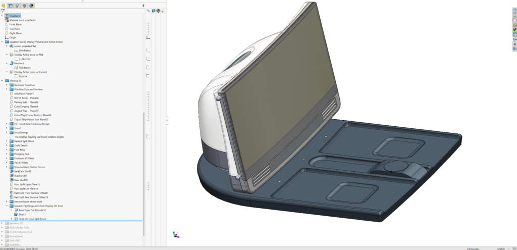
Then I add front bezel detail work like speaker grills, again only as seen from the outside of the product (see “Speaker Openings and clock Display ctrl zone” folder). The goal is to capture ID details without detailing the inside of each part:
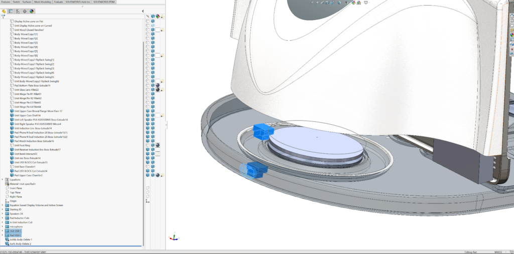
I add speaker volumes as primitive blocks and inductor coils as cylindrical disks (see “Speakers 2X” and “Pad Inductor Coils” folders). If these were real drivers of the form, then I would have placed them higher in the feature tree for referencing. In this case, I figured that if the speaker volumes crash with the inner walls of the enclosure parts, we’ll select new, smaller speakers. In the case of coil selection, the coil diameters really need to follow the outside recess definitions:

I add in the display unit induction coil (see the “In Unit Induction Coil” folder):
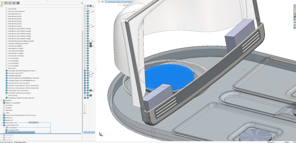
I add simple place-holders for the microphone, connectors, and power connector openings (see the last three folders in the feature tree)
And that in ME_me’s opinion, is all that’s needed to capture initial pre-detailing design intent for ID MM1. There are no external references, because everything is included in this single multi-bodied part file.
Using words and screen grabs to describe any master modeling process is difficult. The best way to examine and understand the finer points of the build is for you to download the file and personally roll through it feature by feature, even opening sketches of features (or editing features) that look new to you.
Developing master models is personal and subjective. My workflow is likely very different from yours or your colleagues’. Some designers will look at this and say I’ve gone over the top (especially with the global variables or so many bodies in my MM). Others might say I haven’t gone far enough, or that my ID form isn’t coupled tightly enough to function with internal component volumes. It’s often unclear when one has done enough to reasonably move onto MM2 or directly to a top-level assembly. In fact, a designer working solo could do complete assembly and part detailing in one multibodied part file. I’ve done it for simple systems a few times with SolidWorks and many times when working with non-associative CAD systems (it’s a great way to stay fluid and avoid external references). But with SolidWorks, it’s only effective and easy if you’re working alone.
Urgency to work with a team is often a key reason to move to a top-level assembly with inserted component parts and subassemblies. I like to work in a single part file until I need to create separate files with unique part numbers to satisfy clients, suppliers, or to bring in team mates. In this imaginary project, my teammates are available and getting restless. So I draw the line here, having thoroughly captured the ID. I quickly create a master model 2, accepting that it is likely incomplete. Unlike the ID capture of MM1, MM2 is simple and minimal. It should be easily understood by engineers only vaguely familiar with the design. It needs to be easy and obvious to use and reference. The bulk of the complexity and relationships between parts have been defined in MM1. If there are required changes to the ID form down the road, a teammate or I will implement them in MM1 so that they’ll ripple across MM2. If there are mechanical components to be added or fastening zones to be refined, we’ll add that detail to MM2. Whether we add to MM1 or 2, we expect that the changes will ripple easily across all affected part files. If they don’t, the fixes required for individual parts would have been necessary regardless of our workflow.
Building MM2 (Master Model 2)
This is the part file I created for ThreadWarp MM2: → “01025-100-0005432 – THREADWARP MM2 ARCHITECTURE AND INTERNALSREV02V19.SLDPRT”
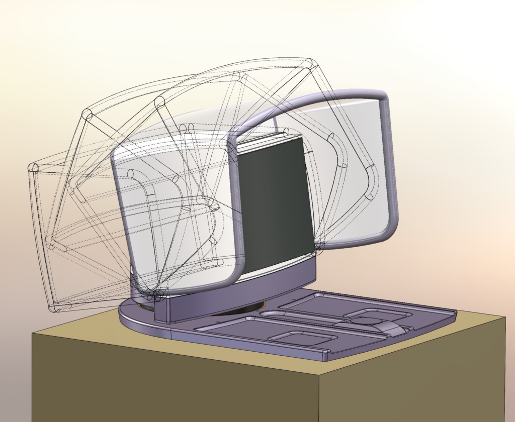
This file will be the one that we insert first before starting the detailing of individual parts (the parts that will populate our top-level assembly). Let’s take a look at MM2 in an earlier pre-released state:

It had 27 solid bodies, three of which are the hood in important end-of-travel orientations, fully closed (against the display screen), flipped back fully open, and in light-blocking deployed ‘blinder’ positions. Of those 27 bodies, 25 originated from MM1. I only built two new bodies in MM2, “PCA PAD ME_REF_ONLY Boss-Extrude1” and “Unit Lens Glass Draft1”.

At this point, I’d also included 6 axes, 24 datum planes, all from MM1 and 90 sketches, 84 of which originated in MM1 (… gulp!). Nobody wants to look at 24 datum planes to try to understand someone else’s “design intent”. Nor do they want to review 90 sketches, especially when most of those sketches’ names give no hint of what they’re for:

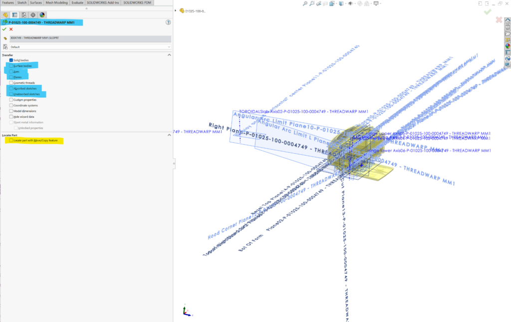
When we insert MM2 (into our individual parts) we have options regarding what features we want to insert. Regardless of what we pick, we’ll get geometry presented in folders containing named (hopefully) but featureless non-editable data. After reviewing the sketches, axes, and planes coming from MM1, I opt to only keep the bodies. My teammates will be able to reference any of the body geometry (faces, edges, etc.) and if I really feel they need new datum planes or sketches, I’ll add them to MM2 as needed as we go. I edit the “insert part” feature (that inserted MM1) and turn off “Surface bodies”, “Axes”, “Planes”, “Absorbed sketches,” and “Unabsorbed sketches” in insert options. When working with master models, one should never check the “Locate part with Move/Copy feature” option, which I’ve highlighted in yellow below. The parts orientation was set when I started building MM1, and all subsequent inserts will load properly without locating or mating:
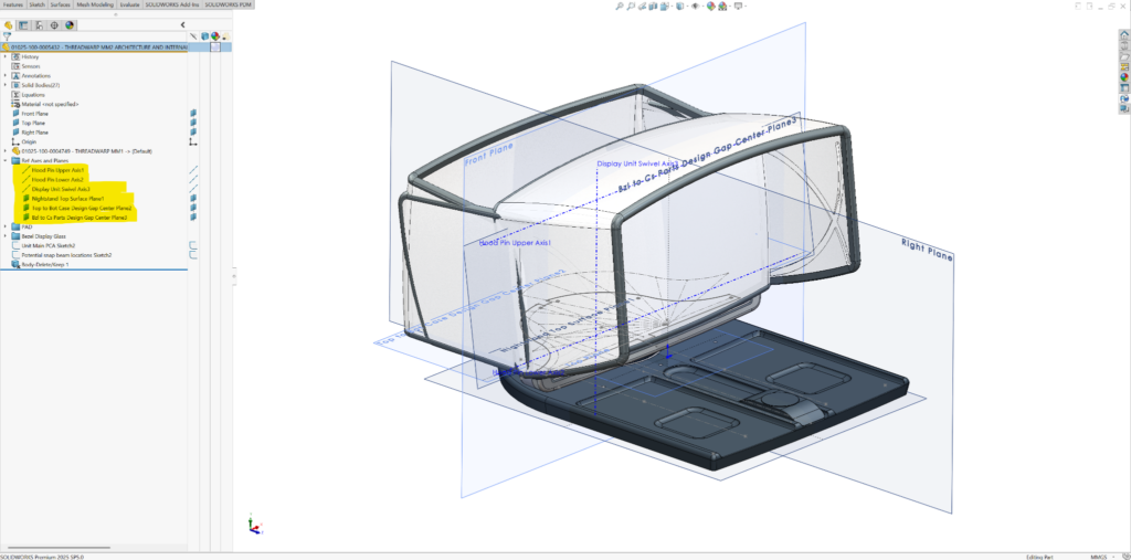
I decided to add 3 reference axes and 3 reference planes that may be useful. I inserted them in the feature tree before the work I did to refine the charging pad and inside the display glass. I add a placeholder printed circuit board blank in the charging pad and a sketch of a potential board outline for the display unit. When we insert MM2 into our component parts, we’ll turn off “Surface bodies” and “Absorbed sketches” and leave “Solid Bodies”, “Axes”, “Planes,” and “Unabsorbed sketches” on. The following screen grab shows all the data our part designer will start with (this is the released MM2 you’ll find in the pack and go files).
I’m ready to populate the top-level assembly, so the team can get started with the detailed design of their parts and subassemblies. Check back for Part 3 in the master model series to learn how to create the top-level assembly.