Article
The Power of Master Modeling in SolidWorks

May 8, 2024 ...
This blog thread assumes that you are familiar with or are a SolidWorks user (‘23 and up). These posts should help you understand how to use master modeling and the choices it brings to real-life product design & development process in fields including consumer electronics & accessories, medical device development, other subsectors of healthcare, and technology product development in general across a wide range of industries. The concepts covered should be helpful, even if you ultimately decide not to use master modeling in your physical product development work flow.
I’ll make files, folders, and myself, [email protected], available to help us both become better design engineers (if you reach out, ask questions, suggest alternatives, or tell me why I’m wrong).
What is a master model? Why does master modeling matter?
A master model is a single file, that, much like a mechanical layout, diagrams how the various features/components of an anticipated system relate to each other spatially. The designer creates the master model and then either “pushes” out individual parts from it as their starting points (i.e., right at the top of their feature trees) or “pulls” the entire master model in as the first feature, again right at the top of the parts feature tree, so that its information is available for referencing in all subsequent independent detailed part work. If the designer has used a “pull,” they’ll want to use the delete bodies (surface and solid) command to eliminate all the information they don’t need for the part they’re detailing as the second step in the feature tree and/or as the last step.
I have a strong preference for the “pull” technique. We’ll get into that later.
The master model captures the relationships between parts—the locations of things like fastening points, critical component volumes, important datum planes and other parts. Because each part of your design starts with the master model, if you change the master model, your changes should propagate through all your parts automatically the next time they’re loaded.
Ideally, you only need to implement the change once in one place, and all affected parts will change with it. Less than ideally, sometimes modifying master models doesn’t go smoothly, but especially as you get better at it, master modeling can save you a lot of hassle and time. It can help you avoid gross or subtle mistakes, especially if you’re working on specific components of a complex custom mechanical system with many teammates.
The core elements of a master model
A master model:
- is a part file → XXX.sldprt.
- is a collection of sketches, planes, axes and/or from-scratch feature-built-bodies (surface and/or solid) that define and capture design intent for the entire project, not just an individual part.
- defines interfaces that affect multiple parts of the design or assembly
An effective master model captures design intent
It captures design intent by:
- making it understandable, even to engineers who are new to the project
- maximizing the likelihood that design revisions properly ripple across all affected parts
- easing the burden of effectively (or even automatically) communicating design revisions across large or separated design teams
It should be created BEFORE each of the parts/components of the assembly(ies) are broken out as individual files. A master model can save you significant time and challenge throughout and especially in the latter stages of a project when changes are often necessary, even after you’ve reached the point of having created many individual part files and a mature top-level assembly.
It is especially helpful when working with outside independent industrial design teams.
What a master model is not
A master model is never
- An assembly file, XXX.sldasm
- A top-level assembly (TLA)
- A configuration or default configuration of an assembly
- A fully detailed individual part file with a collection of bodies that define that one part
Each item above can be useful or necessary for projects but serves a different purpose than the master model.
What your primary goals should be when building a master model:
- Collect a minimum of surface and datum information – enough to provide adequate internal references for each part of the complete design
- Make a model that will ideally automatically drive the propagation of revisions across multiple parts of the project when the geometry is revised in the master model
- Capture your design intent: the relationship between parts, the way they interface with each other, how internal parts drive the design form/geometry, or how ID requirements drive the geometry implementation. That’s a long winded way of saying that master models capture how form follows function, or dare I say it, vice versa, how parts design follows ID form (or user interface requirements).
Since we use master models to ease iterative, incremental, and sometimes significant changes to the design, we try to anticipate the kinds of changes that might be coming to our project.
It’s not easy to predict revisions at the start of a project. But frankly, that shouldn’t be the main goal of master modeling. The challenge of predicting what changes might be needed, coupled with a fear of fixing mature independent parts after revising the master model is why so many great design engineers avoid them. They’ve got the design intent in their heads, they’re understandably trying to stay fluid and likely in a rush. So the potential rewards don’t seem to justify the risk and extra early effort. What they may not realize is that:
- they’re likely building the equivalent of master models at the outset of their projects already and then just rebuilding their parts from scratch after having learned from the early concept work.
- master models come in many flavors, some quite short and simple, some much more complex – the designer gets to decide the master model’s scope.
- master models don’t need to be completely planned out with comprehensive foresight of problems to come, they can always be revised and edited later.
That 3rd point above is one of the main points of this blog: by necessity, master models are living documents, usually incomplete at the start. We work to define them in ways that make them easy to modify or add to as the project evolves.
While dealing with the dynamic demands of a project, deciding the following are some of the most challenging aspects of using master models:
- What level of detail to put in the master model
- Whether we need to do nested master models – where
- the first master model (MM1) captures basic industrial design form and basic external parts breakout (or splits), and is then inserted into the top of
- the second master model (MM2) which captures extra detail like internals (aka the guts) and refined architecture
- When to transition from master models (MM’s) to individual independent parts inserted into Top Level Assemblies (TLA’s)
- How to make changes to the design and individual parts AFTER initiating a top level assembly. In other words, whether to implement the change at the part level or in the master model.
Internal vs. External References, another way to look at master modeling
Another important takeaway from this blog: when working with SolidWorks, use of too many or even any external references can lead to real difficulty. I ALWAYS DO MY BEST TO KEEP ALL REFERENCES INTERNAL.
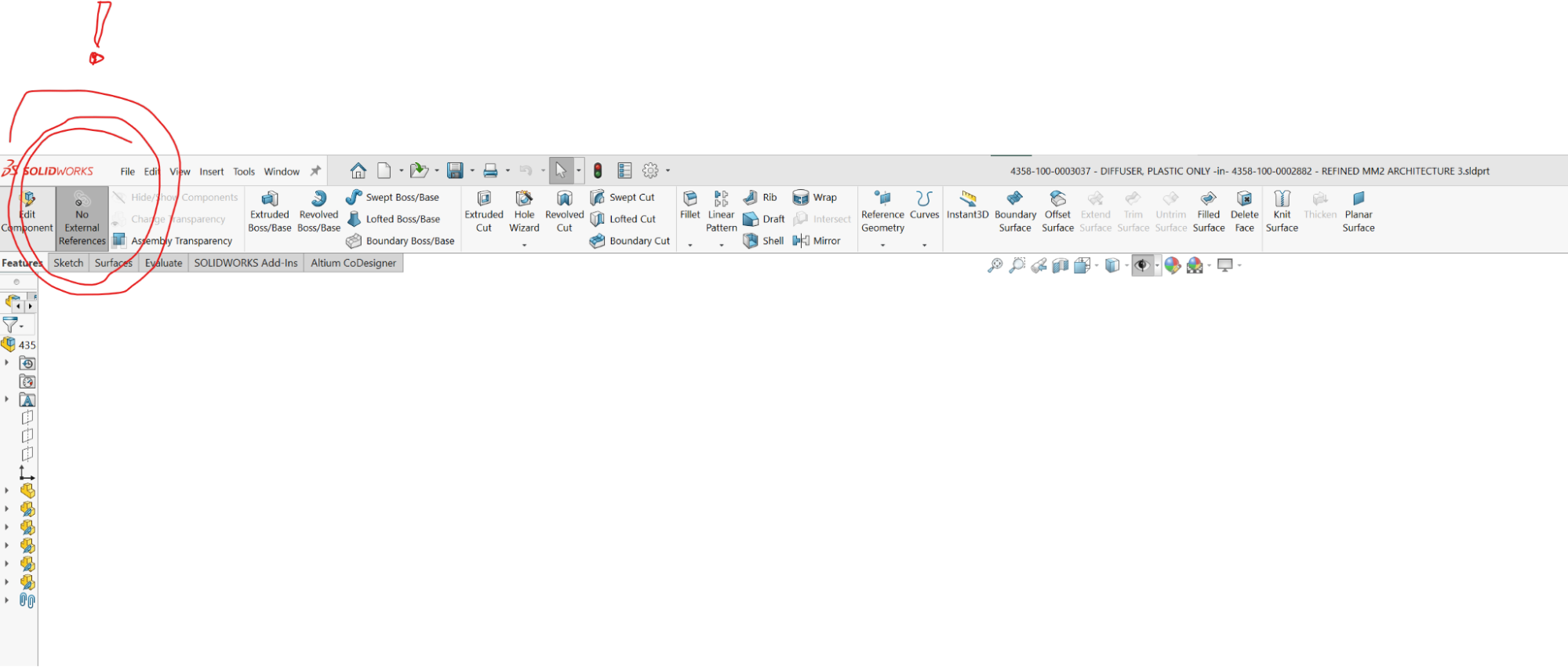
When working in assemblies, I usually and practically exclusively work with external references turned off (see image below). On the rare occasion, always late in the game, that I reference a different part’s surfaces or geometry while editing a part in context (from within an assembly), I accept that the change won’t follow the referenced item if it changes down the road. In other words, it’ll be up to me to remember to fix it if the referenced item changes in the future and it affects other parts.
Master modeling techniques enable you to establish relationships between ultimately separate parts while KEEPING ALL REFERENCES INTERNAL to the standalone part file.
If you’re editing a part in context in an assembly and referencing surfaces or other features of another part with the “No External References” button toggled off, you are creating external references. This can inadvertently create circular logic and lead to scenarios like:
- You modify your parts in an assembly in a session; everything is looking great.
- You save your work.
- You come back the next day in a new session and
- A particular part or even many parts don’t rebuild properly. 🙁
These situations are challenging to recognize, troubleshoot, and fix.
For the reasons above, Fresh generally starts any project with ONE multi-bodied individual part file to represent a design that will become a collection of parts or a system that will ultimately become an assembly file with multiple parts or components ‘inserted.’ Long before a master model is created, our industrial design team uses individual independent multi-bodied part files to capture unique form studies and to iterate on design concepts.
And that brings us to our example project, ThreadWarp. (I wouldn’t blame you if you’re thinking, “finally”. Thanks for reading this far. From here on it’s examples you can poke and prod).
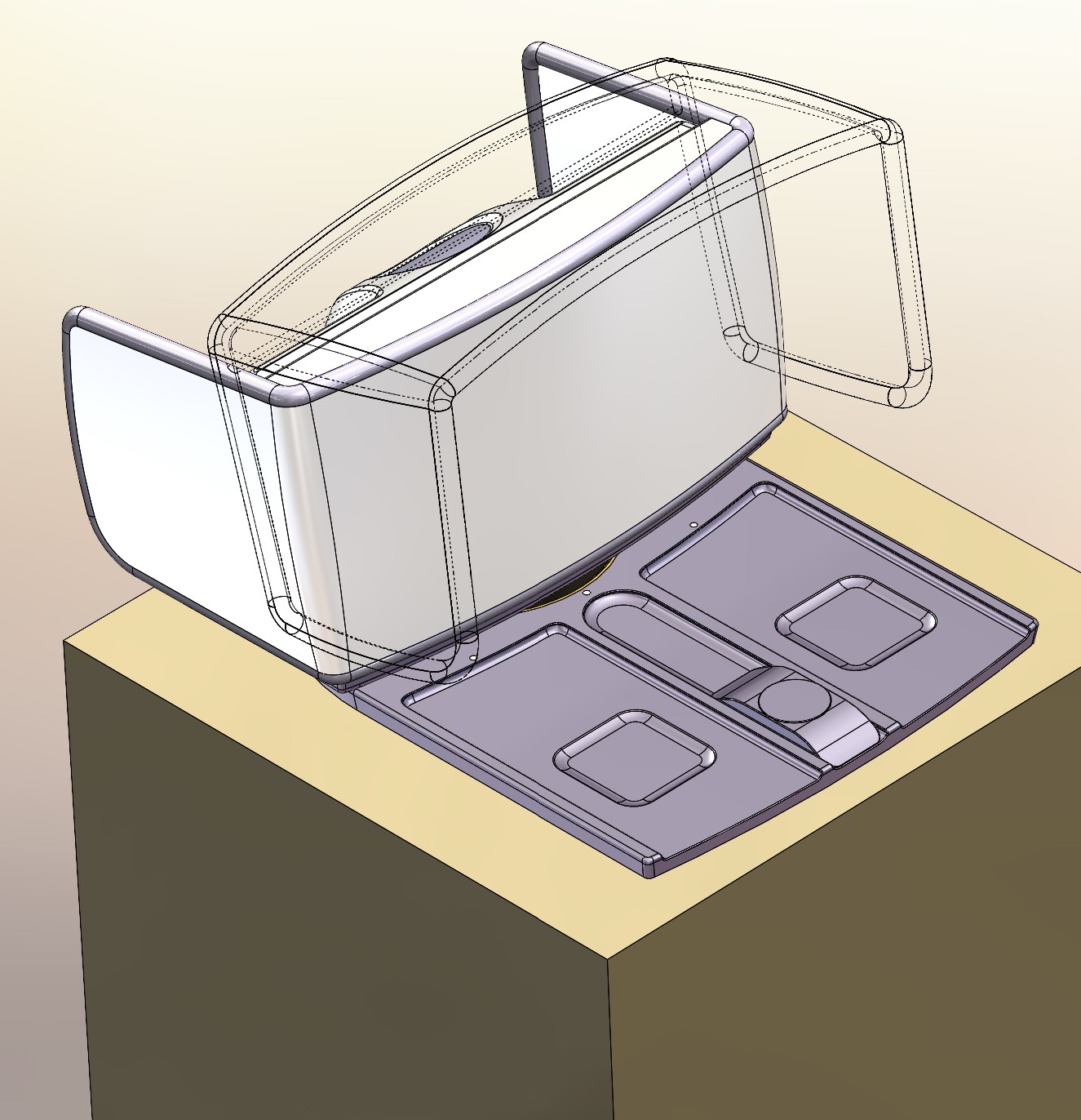
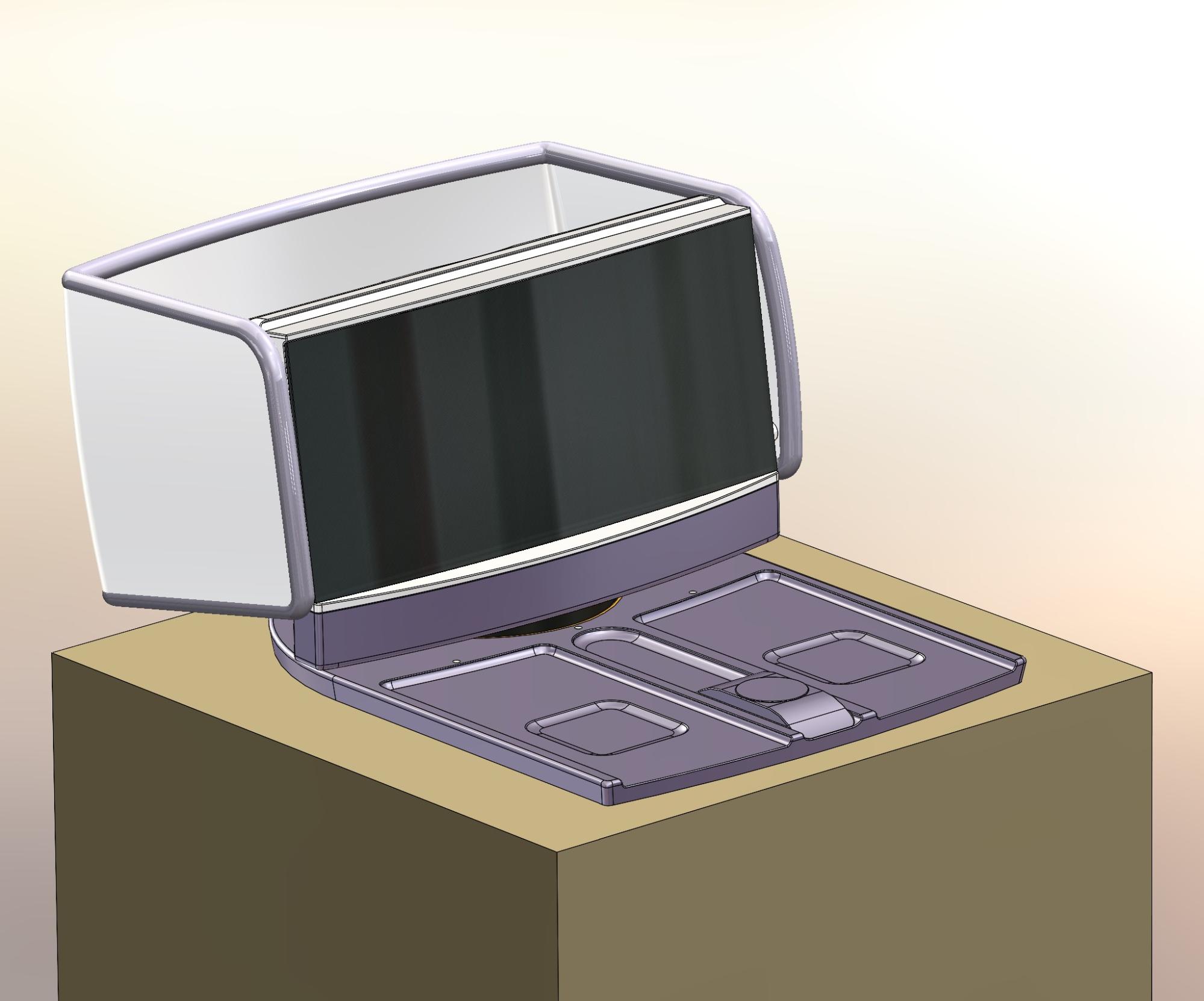
The consumer product project, code-named “ThreadWarp,” is a bedside audiovisual terminal/monitor and personal device charging system that promotes good sleep. It also provides insomniacs with ways to view content on an enhanced screen without bothering their sleeping partners. This bed-top friendly product can also share high-quality streaming audio videos with partners.
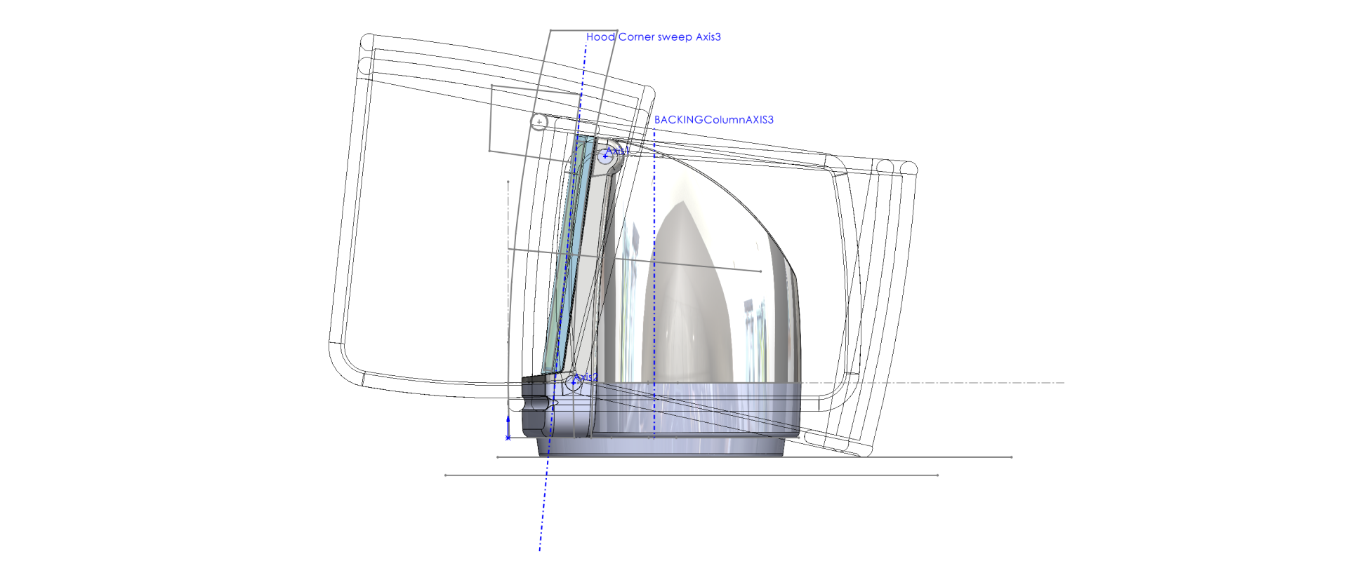
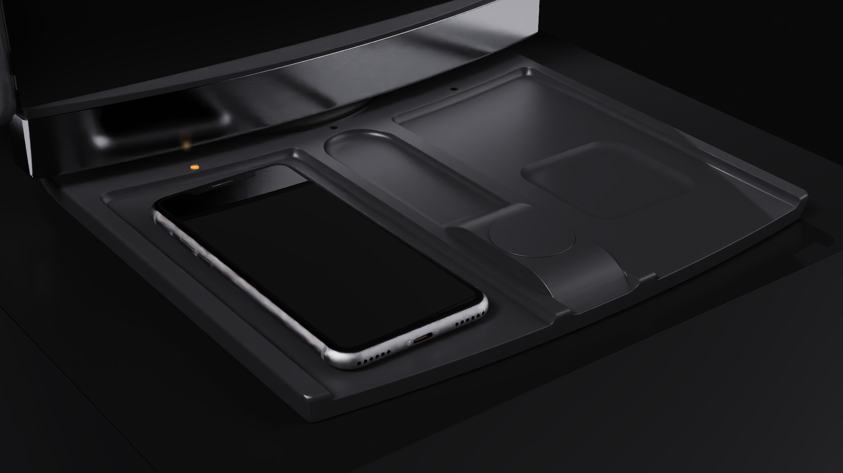
The product provides audio and lighting that promotes sleep, including soothing sounds at bedtime with warm dimming light and pleasant wake-up sounds and light in the morning. It is connected to your smartphone and can also be used to stream music, video, and internet content. It has a special dimmable hood (using the same smart e-dimming tech used in Boeing 787 windows) that blocks stray light during late-night viewing. When not dimmed to be effectively opaque, the hood acts as a light diffuser to create appropriate ambient lighting to promote sleep and wake-up.
Follow along as we design this consumer product, using modeling techniques and master model(s) that we build and update as needed, as productively as possible. When we encounter unexpected developments, we’ll make real-time decisions about how to best pivot or adjust the design in the master model or the downstream affected parts.
Three important disclaimers about this master modeling project
#1: I made this project up, but it’s based on true stories
As a consultancy, creating valuable and often to-be-kept-secret intellectual property, Fresh cannot publish actual designs of real projects. This blog is based on real experiences and recent ongoing work, but it is fictional. I present you with typical problems that arise on projects and share how we deal with them in SolidWorks.
#2: I’m a mechanical engineer, not an industrial designer
Fresh has an amazing industrial design department, who are great at resolving ergonomic and user experience challenges in beautiful ways, in use cases such as IoT product development, RF-based devices, and much more. I’m in the mechanical engineering department. Fresh’s industrial design department was not involved in this imaginary product’s feature or form development—just me. So if you like it, well, thanks! But if you don’t, please accept that aesthetics and human factors excellence are NOT the point of this blog, and this design does not reflect our industrial design team’s skills and talent.
#3: I’m also not a strategist
Fresh has a brilliant strategy team. Providing a range of innovation-as-a-service offerings, they help our clients ideate, develop, and assess business models, product feature sets, and marketing and distribution schemes from the outset of projects before heavy investment is made. Fresh’s Strategy team was not involved in this imaginary project—just me. If you like the feature set and configuration I’ve created, hurray! But if you think it’s crazy, please know that that’s entirely my doing and does not reflect our strategic strength.

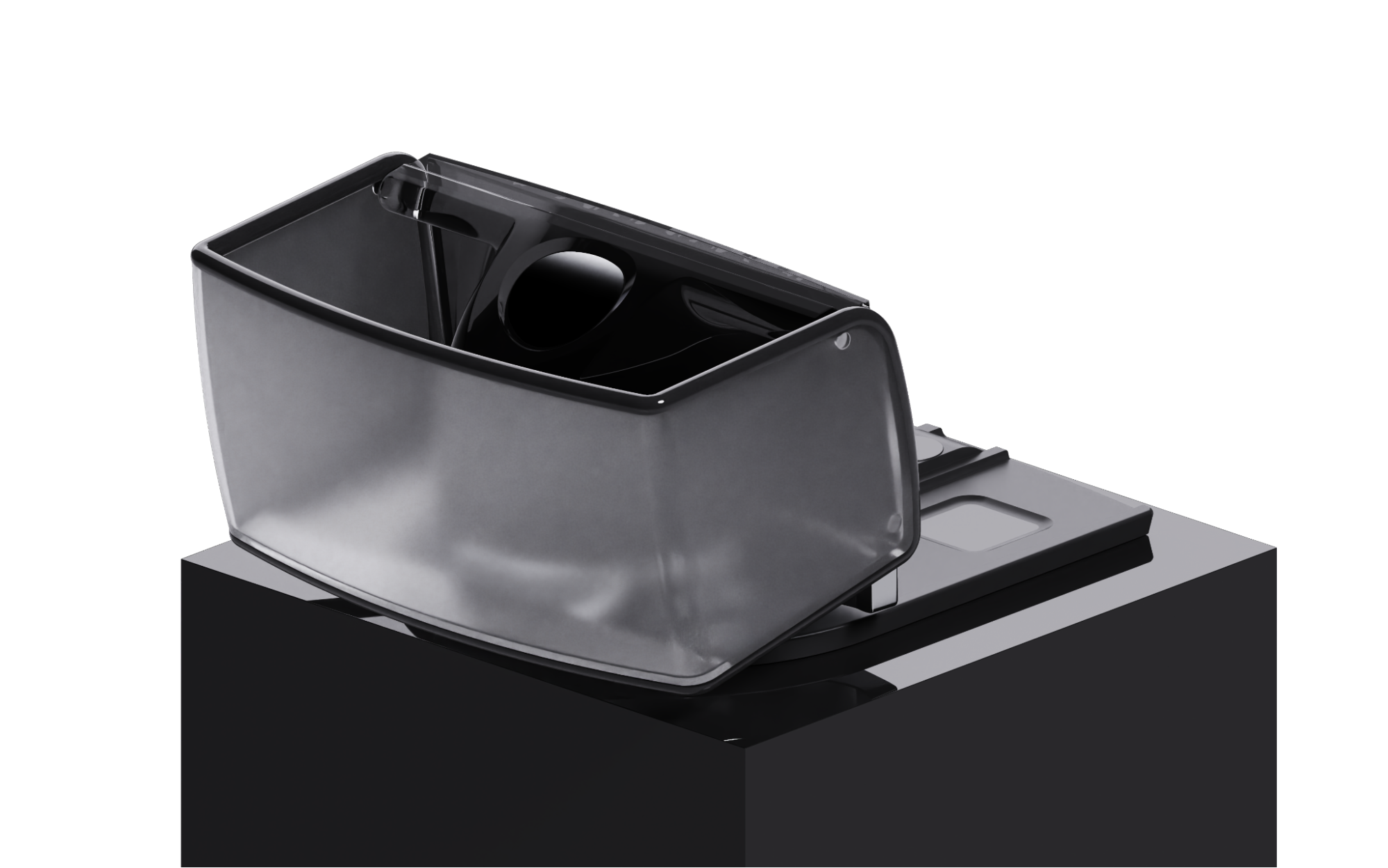


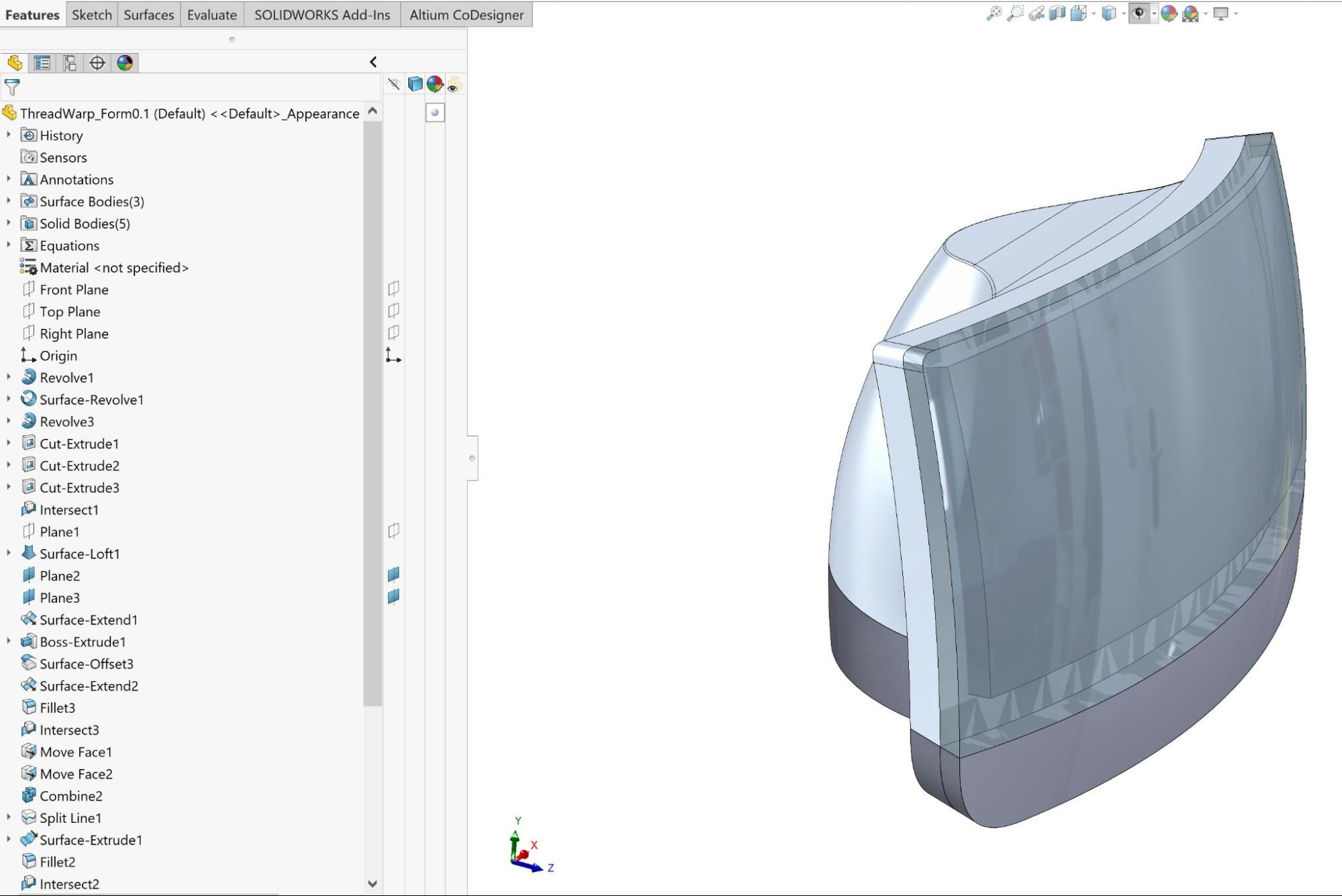
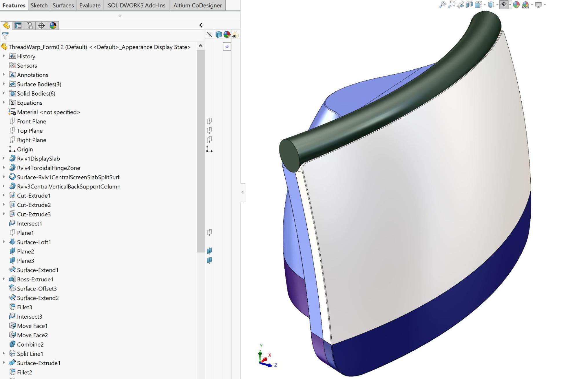
The rendered images above represent an early industrial design concept stage of the design, not the finished product. All sorts of details are missing, even from the industrial design team’s viewpoint. But the images represent a project stage when a Fresh mechanical engineer might be approached to start thinking about product architecture, how the various parts might be built, and how the engineer might build a master model to help realize the client, industrial design, and strategy team’s vision. It represents a point in the project when an engineer is asked to consider how to take the project from concept to a reliable, manufacturable, commercially viable product design.
The industrial design team will have iterated form and concept studies, each version captured in a multi-bodied part file.
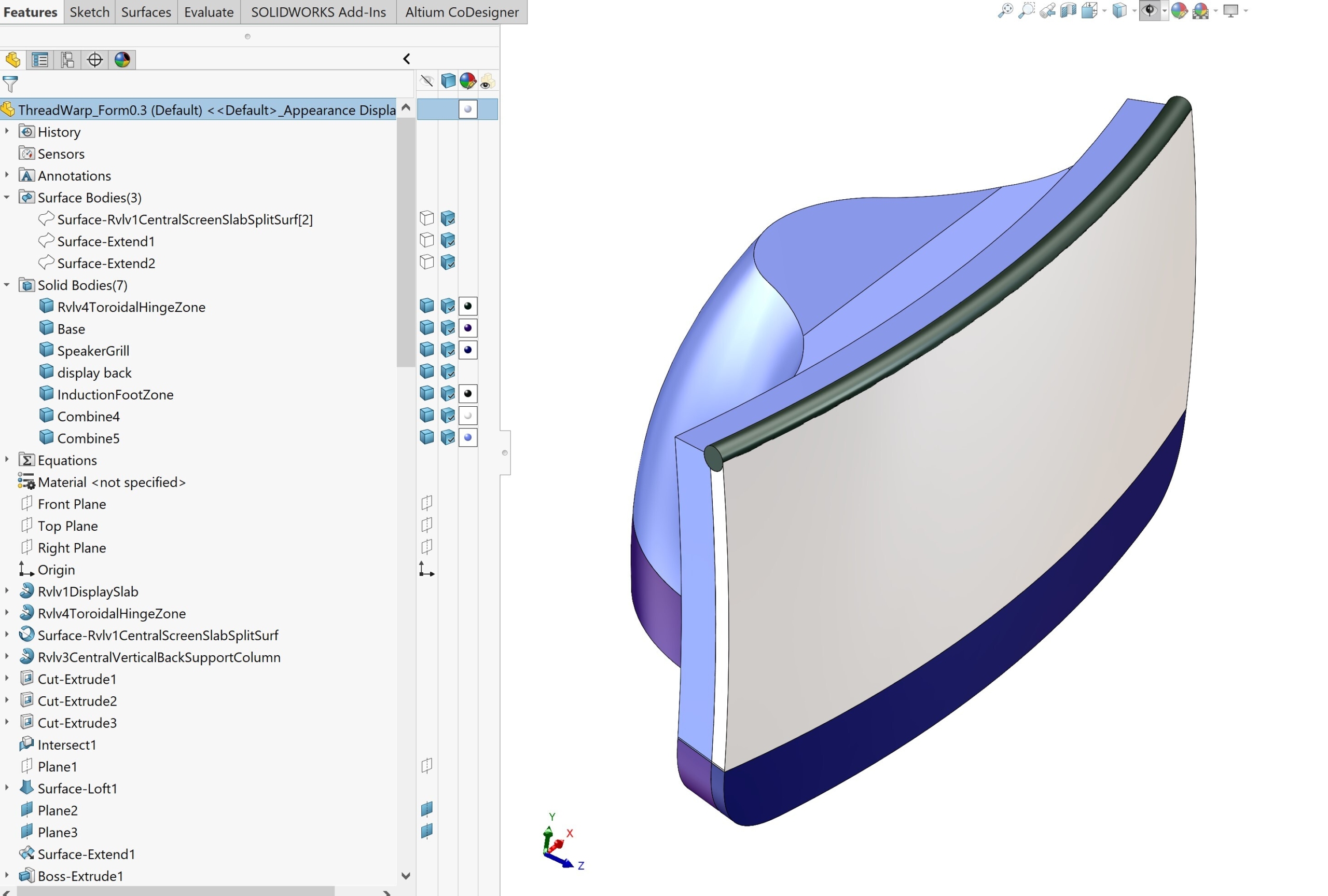
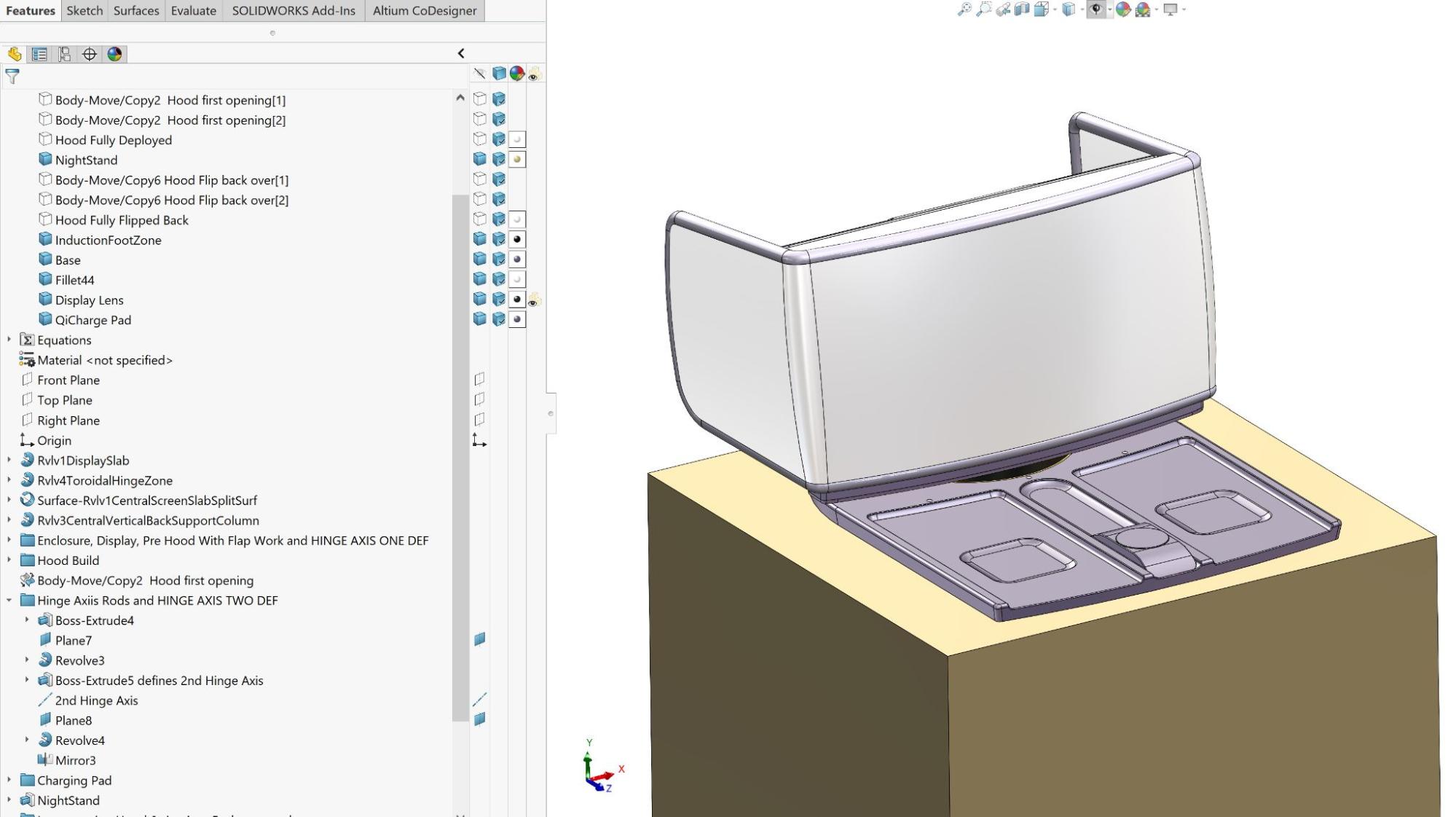
Here’s a sequence of screenshots, from form revisions 0.1 to 0.7, created in SolidWorks by me pretending to be the industrial designer. I’ve no idea if my iterative technique and ‘save as’ points (rev. decrement points) are similar to the approach of our industrial design team. That’s a fairly personal thing, and as I’ve mentioned, I’m a mechanical engineer by trade. But note that the earlier revision feature trees are less labeled and organized. I’m learning about the design as I go and I’m not overly worrying about capturing my design intent. I’m attempting to be fast and fluid.
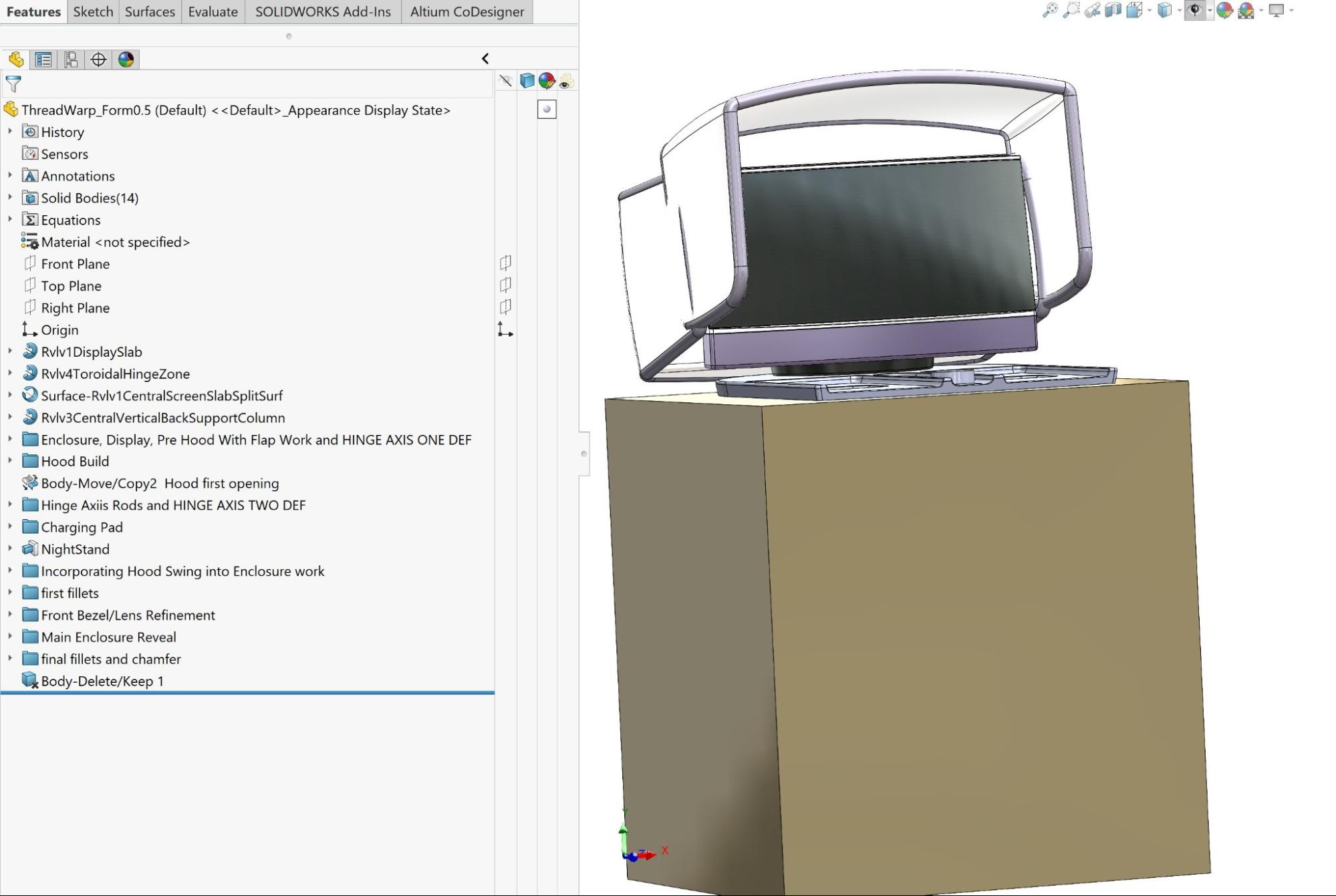

Form study 0.7 is the industrial design rev. brought to the lead mechanical engineer (also me in this case). Here is a downloadable SolidWorks’23 part file of form 0.7 so you can see how I created the features: ThreadWarp_Form0.7.SLDPRT
While building form studies 0.1 through 0.4 or so, I really didn’t worry about how I was building the geometry. In the master modeling workflow, I was merely ideating with an open mind and wondering about how I’d implement the various functional requirements while also considering form. In my humble opinion, the creativity required at the outset of a product development project benefits from unplanned, blue-sky fearlessness. If and when I changed my mind about anything, I just did a ‘save as’ and decremented the rev. number. In real life, there’d be a lot of research, hand sketching, and brainstorming with the client and colleagues to determine what eventually makes it to CAD and the mechanical engineer’s hands.
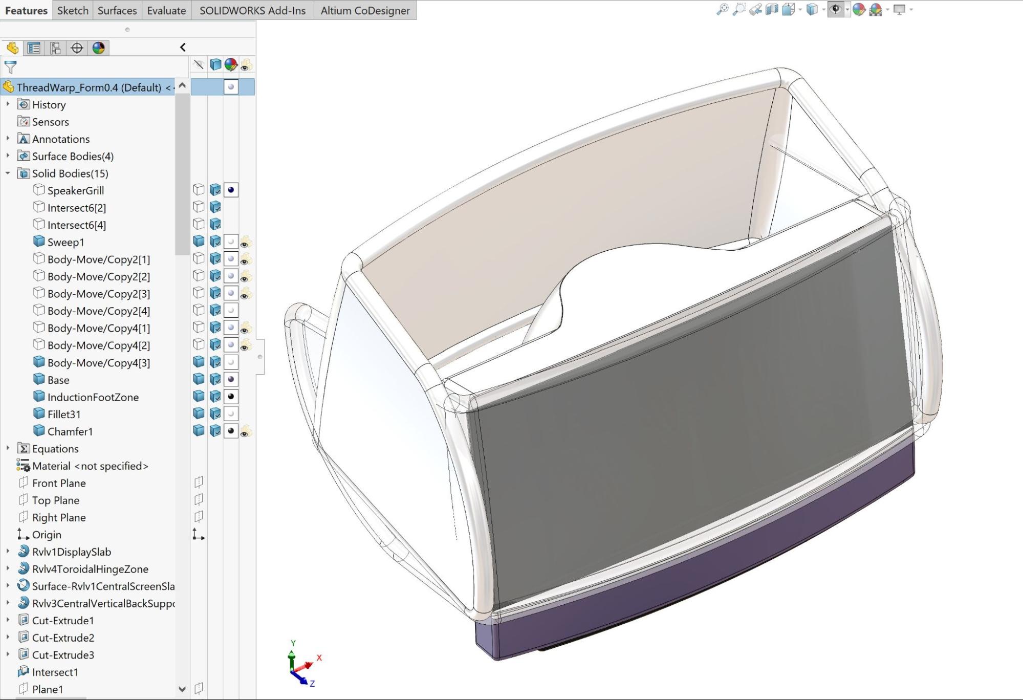
By rev 0.5, I was beginning to understand the relationship between the display and the hood. I was beginning to think about how best to build forms and components in CAD. And because I can’t help but be a mechanical engineer, I’d also started thinking about parts breakout (aka architecture), material, and manufacturing process (in my world, often mainly injection molded plastics), including lines of draft and appropriate part splits.
By the time I reached 0.7, I’d learned how to adjust sketches to modify the track and path of the hood as it deploys and flips back, including how to adjust its shape to compliment the display and enclosure forms in various positions. I also refined the charging pad and added LED charging indicators. If you open the file of form 0.7 you’ll see that we added some speaker holes (not shown below) to the front grill before posting it.

At the completion of this phase of the project, the main goal was to figure out the basic form. Notice that I went to the trouble of organizing the feature tree by grouping various aspects of the design into named folders arranged in a somewhat logical sequence. Whenever possible, I put my fillets (aka rounds) and chamfers one step short of the end of the tree. As a last step, I deleted the extraneous surface and solid bodies.
This organization not only helps a future engineer understand design intent but also helps me organize and revise the design in the future. When the mechanical engineer looks at it, they will likely rebuild the defining industrial design in a more whole-project appropriate manner, benefitting from the effort that has gone before and eliminating external props like the ‘nightstand.’ The industrial designer may not realize it, but they’ve already been applying master modeling techniques to iterate in the concept phase of the project. Note that no assemblies were created so far. Each file is standalone and contains everything it needs.
In the next post, as the mechanical engineer, I’ll rebuild the industrial design from a mechanical engineer’s point of view, possibly checking with the industrial design team as I make tweaks for manufacturability, trying to anticipate likely architecture(s), and then continue to build out the starting point master model, the one I like to call “MM1,” or Master Model 1.
That’s foreshadowing—perhaps you’re thinking OMG, Brad wants to make more than one master model?
Yep.
See you next post! 😉 ).