Article
Master Models Continued: Time for Team work – From Master Model Two to Top Level Assembly

June 25, 2026 ...
This post continues exploring the ThreadWarp project and the master modeling process that is central to our workflow. If you’re wondering how we got here, please check out the first three posts:
- The Power of Master Modeling in SolidWorks
- Master Modeling Techniques, Continued: Keeping the Design Fluid and the CAD Flexible
- Meanwhile, back at ThreadWarp: Further Exploration of SolidWorks Master Models
This and the last two posts reference files from the following downloadable Pack and Go zip archive: 01025-800-0005653 – THREAD WARP TOP LEVEL ASSEMBLY_REV02V19.zip
By the end of the last post, I’d finished building a preliminary master model 2 (MM2) and needed to get the design team started on parallel parts design and detailing efforts. To effectively launch the team and to give them the best chance of leveraging our master modeling to date, I prepare a top level assemby (TLA).
Getting started with the Top Level Assembly (TLA)
As a temporary guide to help me with the parts inventory we’ll be adding, I insert MM2 as a component of the Top Level Assembly (TLA). While it can live here indefinitely, I usually delete it after I’m done populating the assembly. In a completely different approach to master models, one could leave it inserted as a component, edit parts in context, and reference geometry in the master model (instead of inserting the MM as the first feature of each part). This would create external references, but at least they’d all come from the same place.
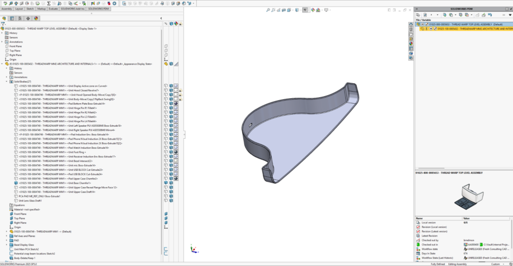
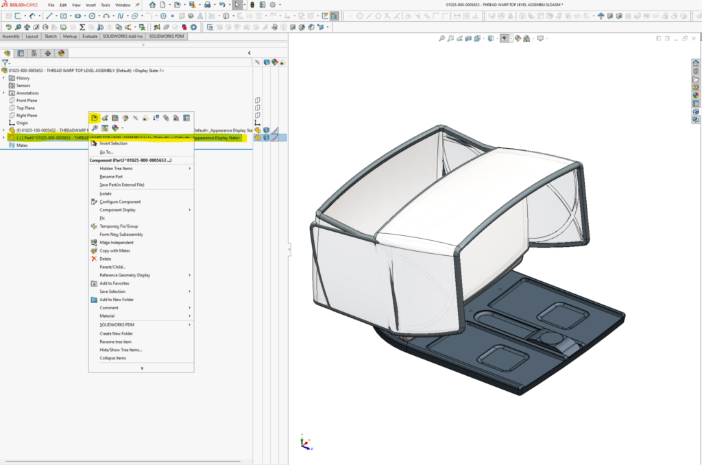
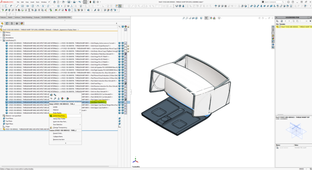
I hide all but the solid body(ies) in MM2 that I want to start with. I note the tail end of its unique body name in the list (“….. >-<Unit Base Chamfer1>”). This MM1 original body will become the basis of the Display Unit’s bottom case part.
I insert a new part component into the assembly (see the following two screen grabs):
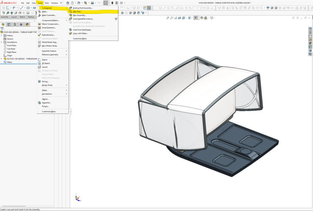
I right-click the new part and open it separately.
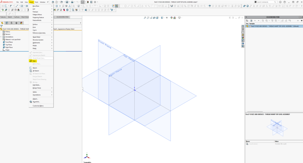
From the opened part file (I still haven’t saved or renamed it), I initiate the insert part command as the first feature of the parts feature tree:
I select MM2 (filename, 01025-100-0005432 – THREADWARP MM2 ARCHITECTURE AND INTERNALS.SLDPRT) for insertion. I’ve chosen to receive “Solid bodies, Axes, Planes, and unabsorbed sketches.” If I decide later that I really needed some other data or didn’t want a previously checked data type, I can edit the feature and change my selections. I like to check “Propagate” Visual Properties “from original part,” (that way I get body, face colors, and visual textures). I don’t select “Locate part with Move/Copy feature”.
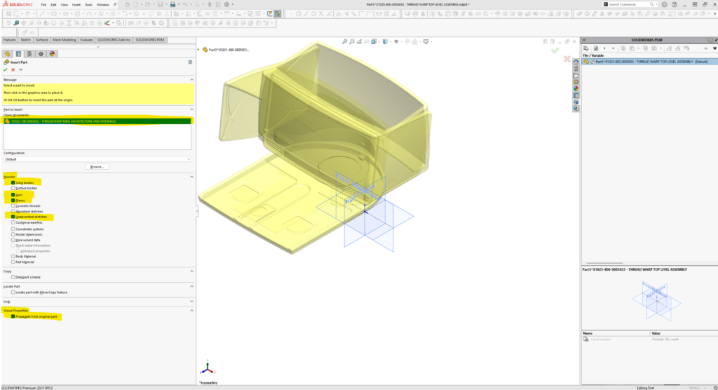
After insertion:
- Only the types of information I checked, if available in the original file, are inserted.
- Front, Top and Right planes of the part are coincident with MM2’s front right and top planes. (even if I don’t check the “planes” box during insertion—in that case, the only planes I have from the first feature will be the global Front, Right, and Top planes of the new part itself, so bodies and other data will be where they’re meant to be from the get-go.
- The inserted part geometry data is placed in folders without its defining feature information. Axes, Planes, and Sketch definitions are locked (not editable). Surface and solid bodies are single featured only, but can be edited, moved, or deleted from their initial inserted condition.
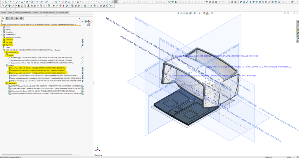
Next, I open the solid bodies folder and select the body I’m interested in detailing. While selected, I right-click it, choose the “Delete/Keep Body” command, and then select “Keep selected bodies.” I could have selected multiple bodies I wanted to keep, or I could have selected “delete selected bodies” rather than keep. But I’ve found it’s easiest and more robust to just select the body(ies) to keep. Later, as detailing begins, I may go back and edit this feature to include bodies whose surfaces, edges, etc. I might need to reference, or I might roll above the delete/keep body feature in the feature tree and begin detailing with all the bodies available for referencing.
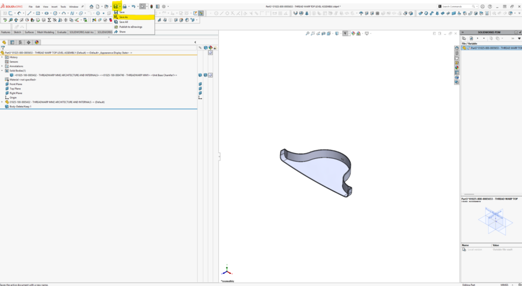
With these two features in place, I do a “Save As” to externalize the part and give it an appropriate part name.
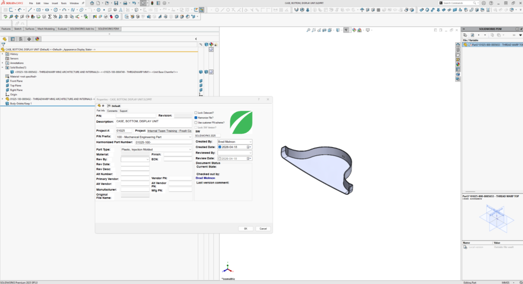
At least in a PDM environment, you’ll be prompted to fill out a data card before the save completes. In our case, I chose to ‘harmonize’ the file to add a unique Fresh part number to the filename.
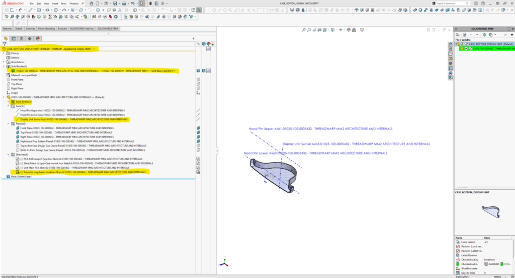
Now the part, “CASE, BOTTOM, DISPLAY UNIT” has its own part and filename. It loads as a single-bodied (for now) part file with important relevant information in the form of meaningful axes, planes, and sketches. As teammates detail the part, they can reference any sketches, planes, axes, or kept body geometry in the part, keeping references internal so that if someone edits MM1 or MM2 upstream, the edits will propagate through their features. As long as they work in the context of their independent part file and avoid referencing other parts while ‘editing in context’ in assemblies, they’ll keep all references internal to the part. “No external references” is my mantra because I believe this helps keep file load times down, eliminates awkward external reference/originating reference file searches, and, in worst-case scenarios, minimizes system crashes.
I repeat the steps above for the remaing individual parts and those that will eventually become subassemblies (they start out as individual part files – xxx.SLDPRT, rather than assembly files – xxx.SLDASM; the hood is a great example). This process takes a while, but it’s well worth it. It’s also a good time to begin implementing a proposed hierarchical architecture (how you’d like the BOM arranged) and assembly sequence of your design.
Let’s examine the team starting point TLA, “01025-800-0005653 – THREAD WARP TOP LEVEL ASSEMBLYREV02V19.SLDASM”:
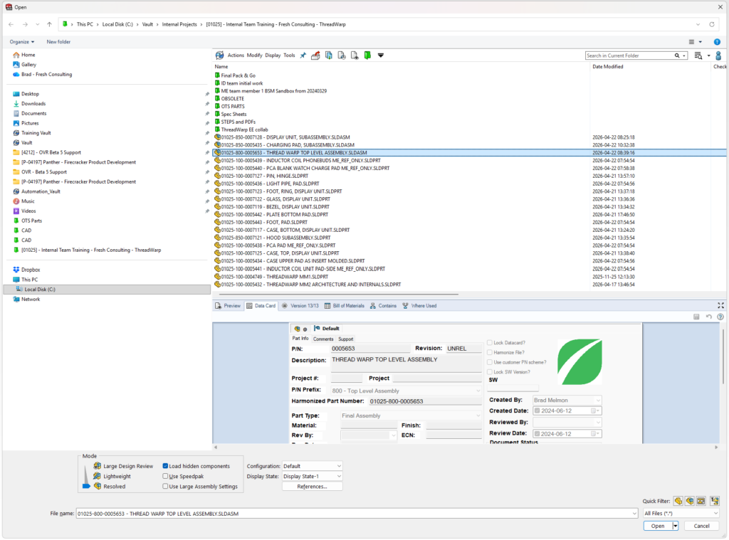
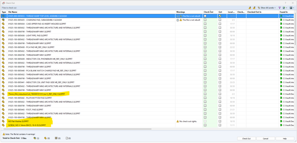
Fresh uses a PDM (aka ‘vault’) to keep an archival history of all of our design work and coordinate team efforts. As I’m getting the TLA, I notice a few files, highlighted below, in our project directory that don’t have assigned part numbers. I take a mental note to move them to the off the shelf, “OTS” folder if they’re actually called by the TLA or delete them.
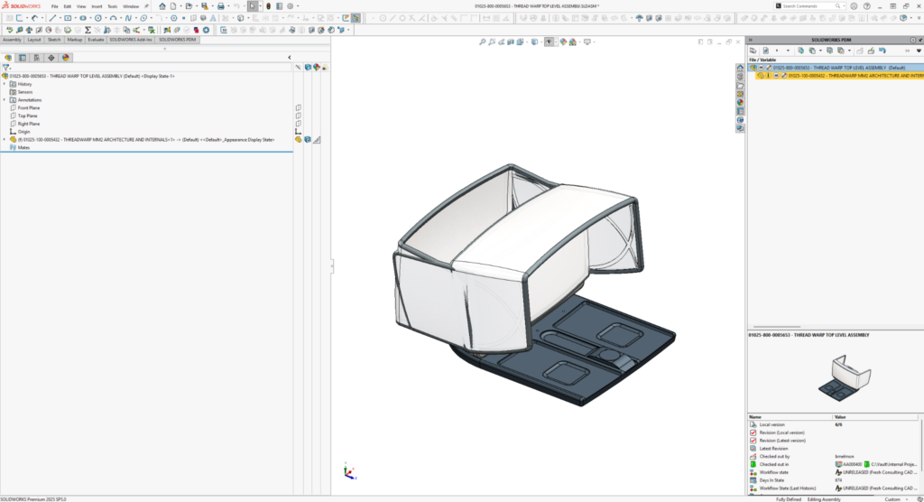
Here’s the loaded TLA. Note that I’ve organized it into two main subassemblies, the Charging Pad and the Display Unit:
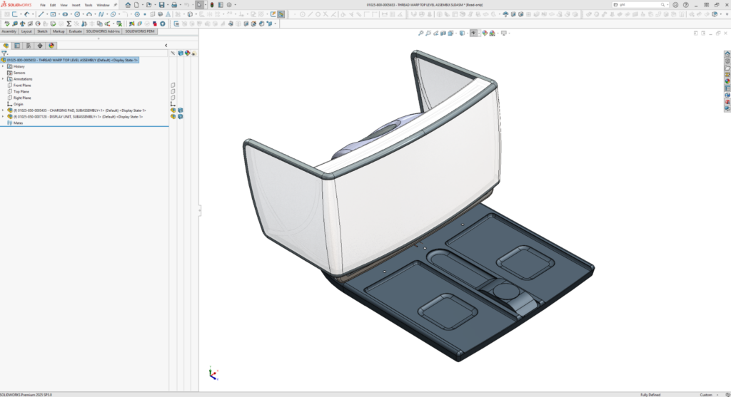
From now on, when any of us need to work on a particular part, we won’t need to load nor check out the TLA. We can just load the part or subassembly in question. TLA’s can get data-heavy and slow. Organizing it this way can improve work efficiency. Each of us only needs to check out a part or parts we intend to edit, leaving the rest free for others to check out and work on.
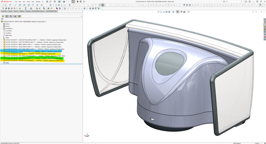
Let’s load the Display Unit subassembly. It’s ready for the team to start from, but there’s work we’ll want to do soon:
- We’ll want to create configurations for the different articulations (currently shown closed) of the hood (highlighted in cyan).
- At the moment, the hood is a part file but titled as a subassembly because eventually it’ll be made up of many parts.
- We’ll want to use the same hinge pin part in all locations to secure the hood, provide for its articulation, and to transmit power for adjusting its translucence. There’s currently only one instance (of 4) of the pin and one instance (of 2) of the speaker (yellow highlighted for both parts). The new instances will need to be inserted as components and mated to proper locations.
- There is only one instance of the microphone (green highlighted), but we may need two. The additional microphone will face away from the user and from internal sound sources (like the speakers). It will be used for “audio difference” operations while listening to ambient background sound.
Let’s load the Charging Pad, Subassembly. We’ve reached a “story within the story” point. I’ve been working on and off again (mostly off again) on ThreadWarp for almost two and a half years. I’d forgotten that the last time I touched the Charging Pad, it was to make it into a standalone assembly so that Mikhail, a lead EE at Fresh, and I could demo the use of Altium Co-Designer as a means for EE / ME teams to collaborate. You can view a video of our demo here:
Fresh Consulting Lunch and Learn Altium CoDesigner Video
At the time, I thought I’d “finished” MM1 and had started on MM2. For the sake of the demo, I broke out the charging pad for further development and incorporation of a printed circuit board assembly (PCA). I inserted MM2 as it was into the parts that made up the Charging Pad subassembly and added the PCA and an inductor coil from Mikhail. I’ve worked on both MM1 and MM2 since then. We’ve upgraded to Solid Works ‘25 since then. Through it all, my revisions and updates have propogated without problem to the individual parts and subassemblies, including the Charging Pad subassembly.
And that’s the point: The master models and their derived assemblies are “living”; they’re not complete until the project finishes. We add detail, take some away, modify, and pivot with revisions in the master model files and expect them to propagate through our design. For the story’s sake, let’s imagine we had available resources to start on the Charging Pad and that our client wanted to lock in its low-risk Display Unit / Charging Pad mechanical interface. So we had our mechanical and electrical engineers sprint ahead – fleshing it out, while ME_me was left to finish updates to MM2. This means, as you examine my pack and go files, that you’ll find many of the parts of the Charging Pad are farther along and more detailed than those in the Display Unit.

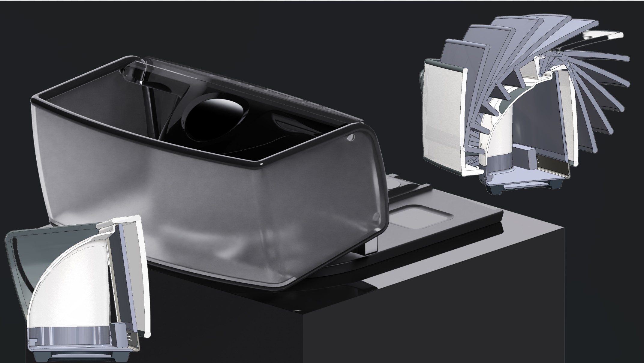
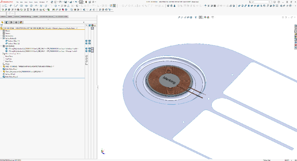
Perhaps you noticed two brown wires poking straight out of the main foot induction zone above. Clients hate seeing this, but it’s no big deal. These are just the leads of the induction coil modeled to length in straight lines. The Charging Pad “ME team” still needs to route the wires along the inner contours of the Charging Pad, top case part. To that end, they rolled up one step above “Body-Delete/Keep” in the part feature tree, (see below) to gain access to the surface geomety they cared about.
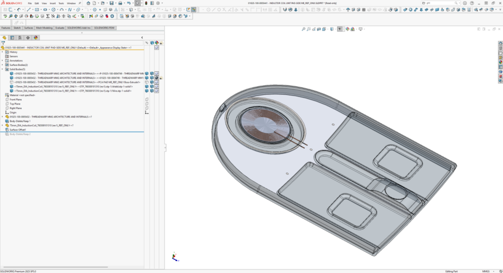
Then they did an “offset/copy” of the faces they’ll need to route around. And then rolled back to the end before saving and stopping their work on the Inductor Coil. That’s what you see below.
How master models and top level assemblies support team-based design
My teammates open the TLA and look through it. We get together and agree upon who will work on each part and subassembly. They each check out their assigned part or subassembly to start detailing. If we bump into problems, need to pivot, or resolve open issues, we’ll decide where to make the changes in CAD:
- in MM1 (if a significant feature or form change affects the exterior ID and human interfaces of the product),
- in MM2 (if only the insides, mating schemes, or mechanical interfaces between parts are affected)
- or to individual affected part files (if no other parts are affected – perhaps for a subtle change not worth capturing in the master model).
If we make changes to MM1 or MM2, all affected parts will update the next time team members get the latest versions from the vault. The ramifications can be quickly dealt with as long as the editor of MM1 or MM2 checks their work in.
Adapting master models as your design evolves
After an initial review, teammate “ME_not-me” points out that I’ve forgotten to put in a placeholder for the battery pack. Ouch! How could I forget such a basic component? So where do we put it? We could insert a new part into the TLA and try to make it fit. But if we do that and its dimensions change and crash into inner sidewalls or other components of the design, we run the risk that not all affected teammates will notice. In theory it could drive the design so much that, like the display, I should put a placeholder in MM1 and even drive the ID from it. But, dang, I’ve just released my TLA to the team. There’s likely room for a battery with the current MM1 ID definition. So I decide to add it to MM2… But not in time for this post. (So it’s not included in the downloadable pack and go).
Don’t be discouraged by the prospect of going back to your master models, modifying, adding, or deleting from them. Of course, the earlier we pivot in a project, the better and easier it will be to implement the change. especially in a master model. If it’s late in the game, you might opt to make the change to an independent, undriven part in the TLA. If you discover a crash that impacts the ID, you could insert the revised or additional part (overlooked battery pack in this example) in the TLA, but go back to ID MM1 to make the accommodating change to its form. For instance, if you grow the bottom case footprint by a millimeter in one dimension or all around, by modifying the footprint’s defining sketch in MM1, other affected features e.g., reveal details between bottom and top cases, will automatically update. Your teammates might not even notice the change as it ripples through their parts! I’ll share examples of revision work, early and late in a project in follow on ThreadWarp & master modeling blog posts.
There’s no one-size-fits-all approach to master models
Both FreshRoll and ThreadWarp are examples of attempts to keep things simple and flexible, though the approaches are different. In both cases, ID complexity is captured independently of the master model that is inserted into parts files. It’s always advisable to consider what you hope to achieve with master models before you start on them, but remember that the model is never a fait accompli – you can always tweak, delete bits, or add to it later.
Thank you for taking the time to read this. I hope it helps your modeling and project startegies and efforts.
Please reach out with questions about master models, modeling techniques, to suggest alternative workflows, blog edits, or to offer corrections.
Good luck and see you next time!