Article
Physical Product Design — Confessions of a Reformed Self-Proclaimed Non-Associative CAD Guru

May 8, 2024 ...
Greetings! I’m Brad Melmon, a lead mechanical engineer, (ME) at Fresh Consulting. I’m writing an interactive blog with two parallel threads covering the evolution of physical product design, mechanical engineering, associative CAD systems, master modeling, and more:
- One thread to introduce you to the general world of physical product design. I’ll talk about the tools and processes designers and engineers used in the past, what we use today and some of the mindsets and processes that bring optimal project resolution.
- The other thread covers the detailed use of SolidWorks, our mechanical engineering CAD platform of choice, emphasizing the techniques and power of master modeling.
I’ll attempt to dive a little deeper into detail with each post than shorter blogs do. To that end, for the second thread:
- I’ll be taking you through an imaginary but realistic project cycle – at least from a process and CAD perspective. We’ll cover the CAD work from early concept phase, through Top Level Assembly build and onto detailed part design.
- I’ll include downloadable SolidWorks, “.sldprt” and/or “Pack n’ Go” files. If you’re running SW’23 or higher, you’ll literally be able to scroll through the feature trees and see how I built them.
Before you start — a note on associative CAD platforms and master modeling in the world of physical product design
I’ve worked with many talented engineers and designers who stay away from associative CAD platforms and even more who avoid master modeling, thinking it’s complicated and rigid—not worth the time. Perhaps you’re reading this blog in the hopes of gleaning what a master model is, when to start or even if you should use one at all. It will be easier for you to answer these questions if you’re aware of a few CAD and general design project “balancing acts” that I describe in this first “Confessions” thread.
But if you want to just cut to the chase, you could start immediately from the second thread, The Power of Master Modeling in SolidWorks. It’s specifically about how Fresh uses SolidWorks and master models.
For a longer, more personal read, please continue here.
Product design balancing acts
Design can be messy, intuitive, and intense: There’s always tension between doing brilliant, innovative, thorough work and getting a good enough design to production ASAP. The tension between time to market and delivering high-quality magic leads to three balancing acts.
- DIY & Release vs. Methodic, Documented, “Managed” Team work
- Intuitive “direct” modeling (aka no-history CAD) vs. “Associative” (history-based CAD)
- Fluid, Spontaneous, then Pivot Design vs. All Planned Out, Methodic Design
Balancing act #3 could be a variation on Agile vs. Waterfall. Being from the physical product design world, these project management process terms’ definitions seem vague, with the reality of product development demanding a bit of both throughout the project.
Balancing act #2 above may seem like a simple choice we make between using history-based or non history-based CAD systems. But even in the associative (history-based) world, one can pay more or less attention to the feature tree, its build sequence and labeling. One can also jump early or late into assemblies of inserted individual parts. So even if you’re history-based, #2 is still a balancing act between not worrying about capturing design intent – just getting it done, and thoughtfully attempting to make the history meaningful and legible, especially to others.
Balancing act #1 is not really about how big the design team is. It’s more about team work style. Are team mates interacting with each other, brainstorming and making decisions together or are they effectively silo’ed from each other – passing pieces of the design over the cubicle wall or from a remote design office to the next team or contributor?
The dawn of mechanical engineering CAD
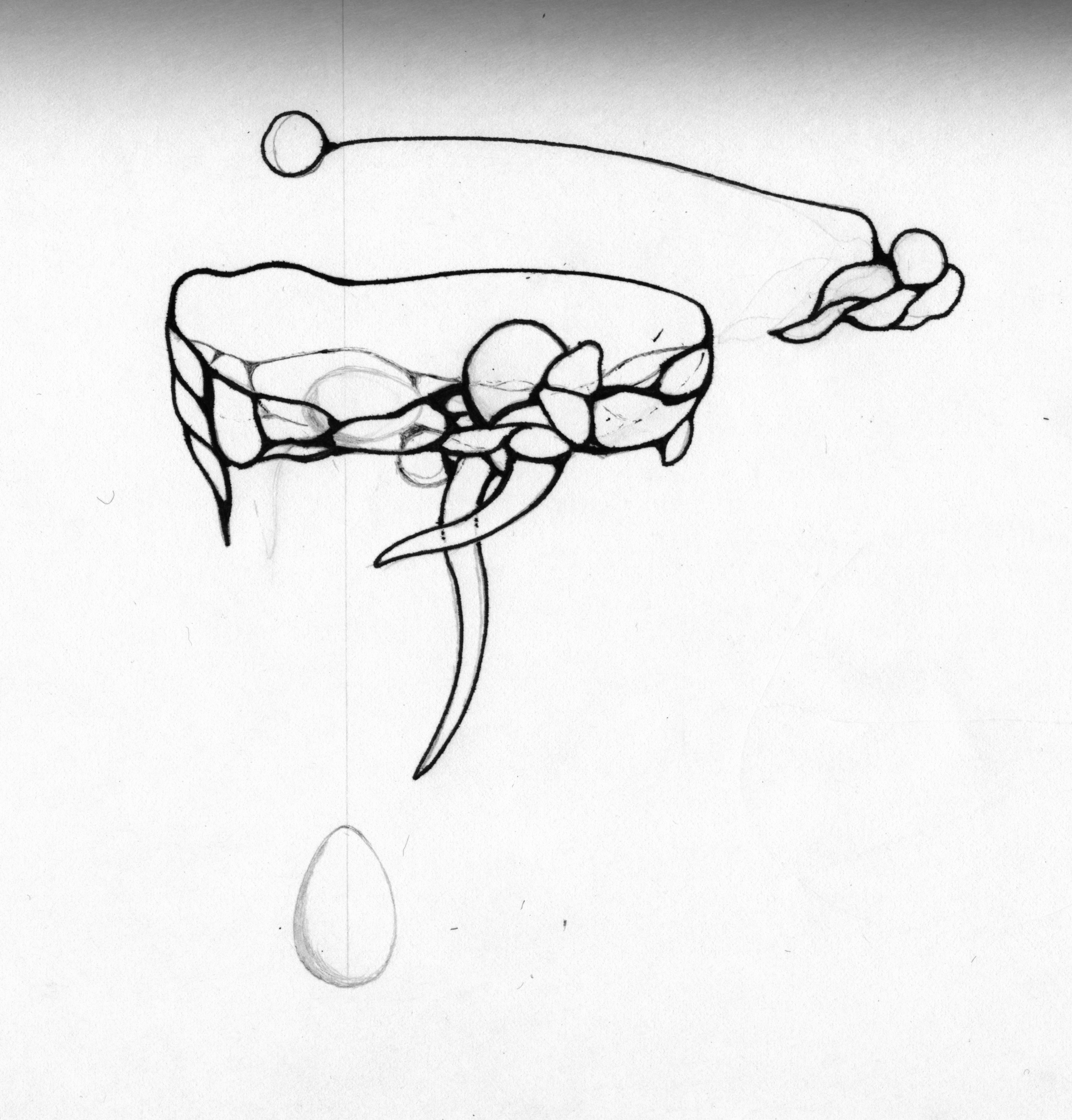
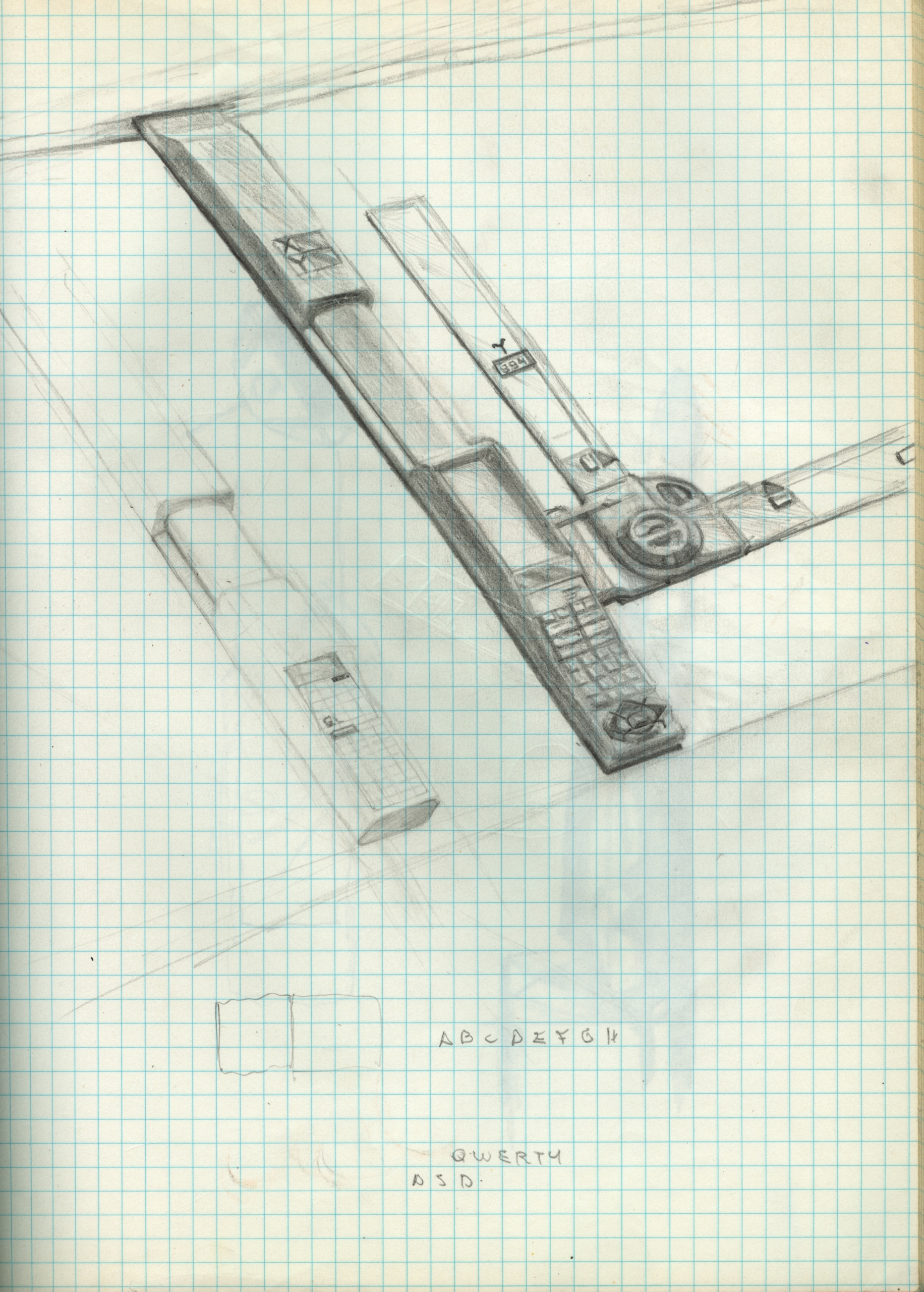
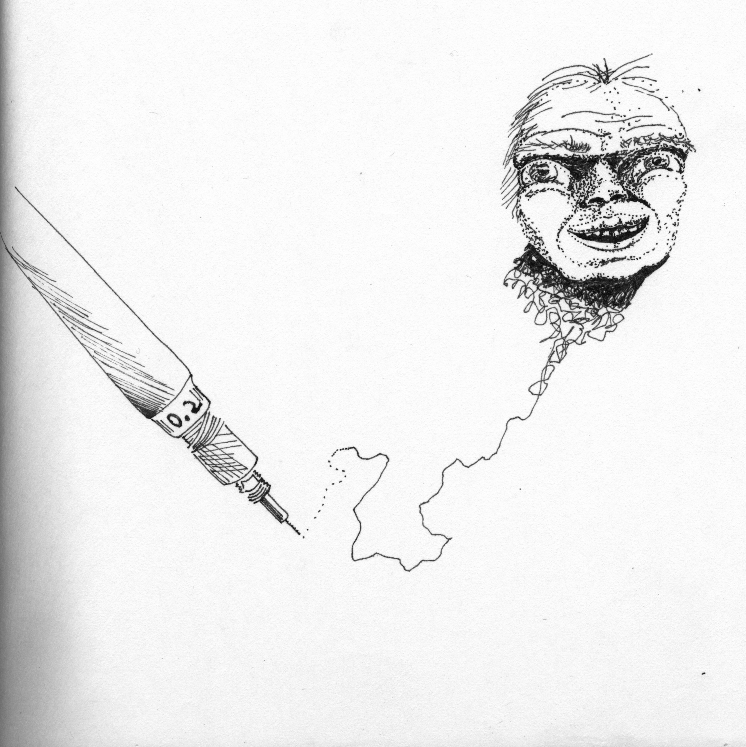
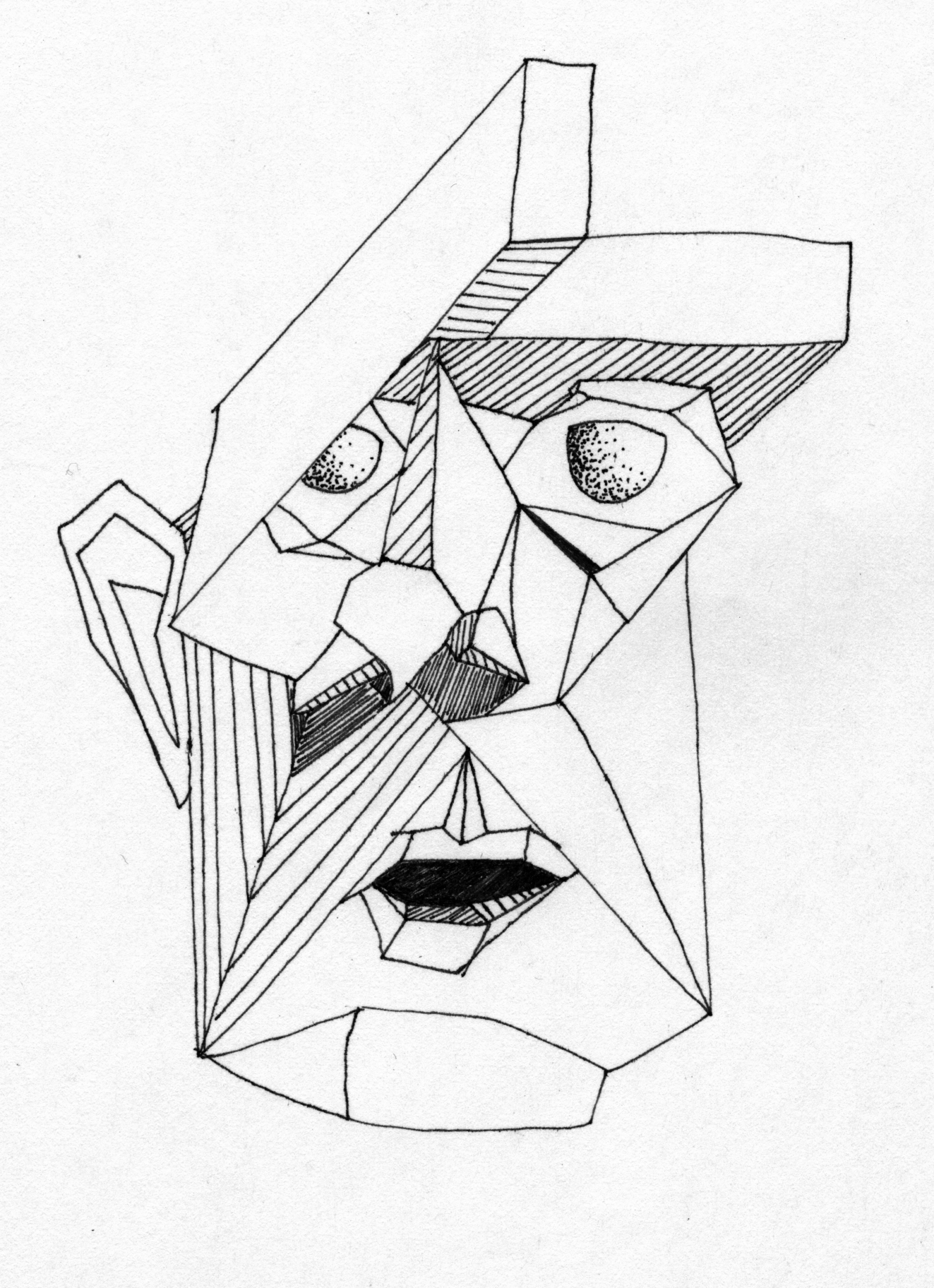
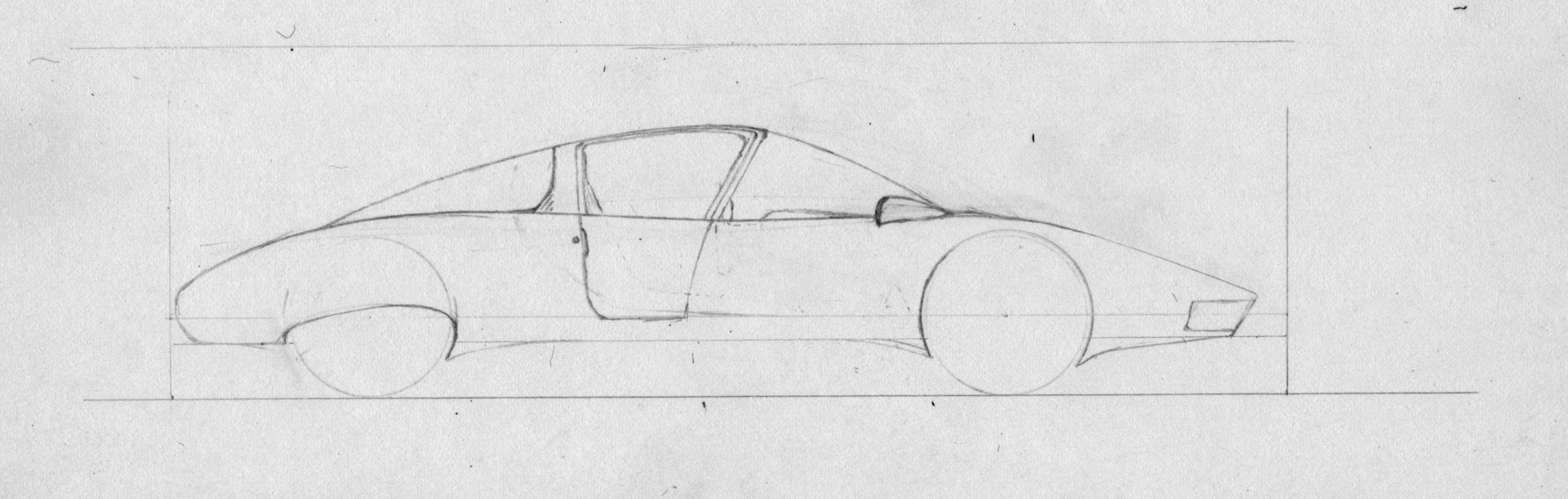
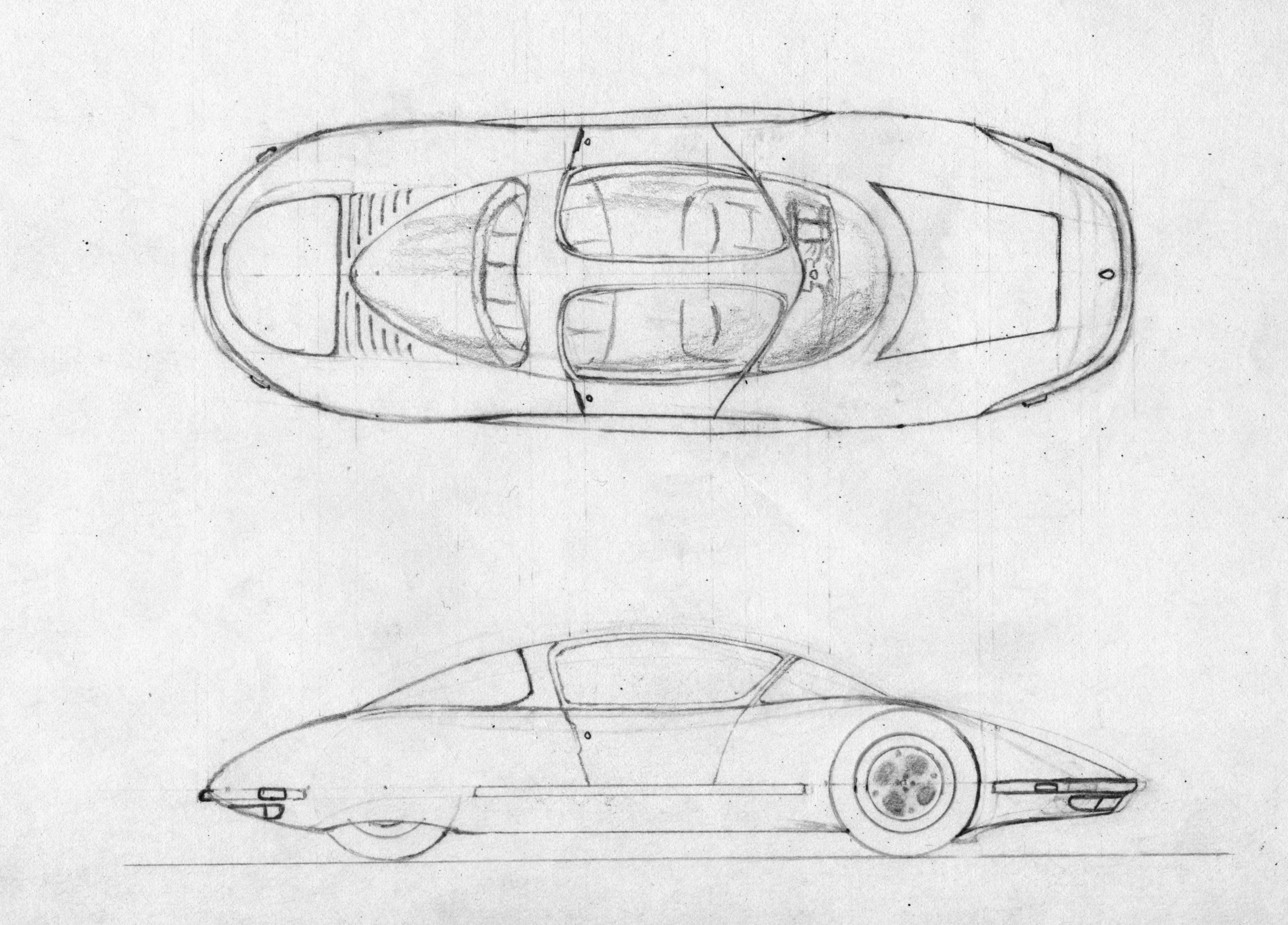
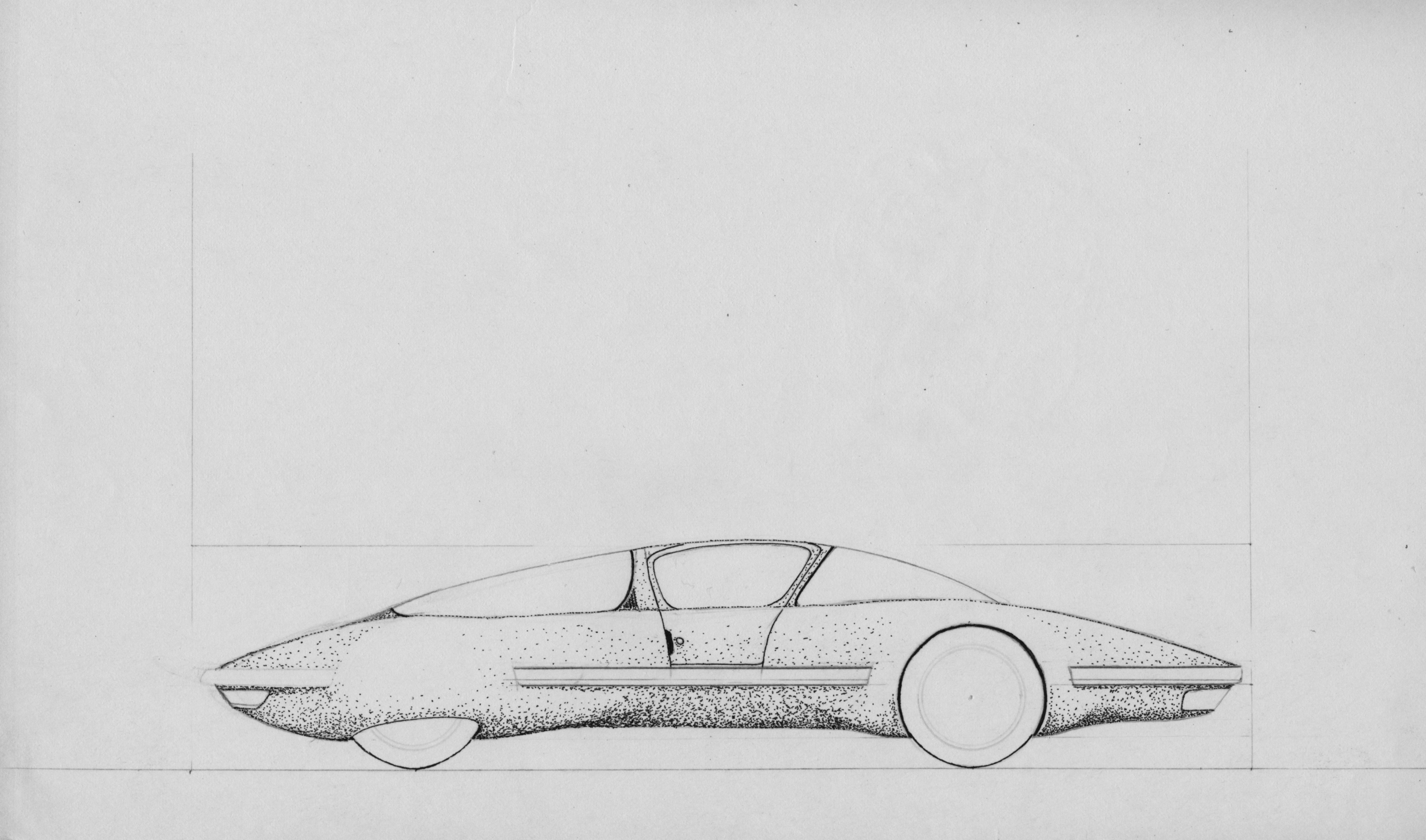
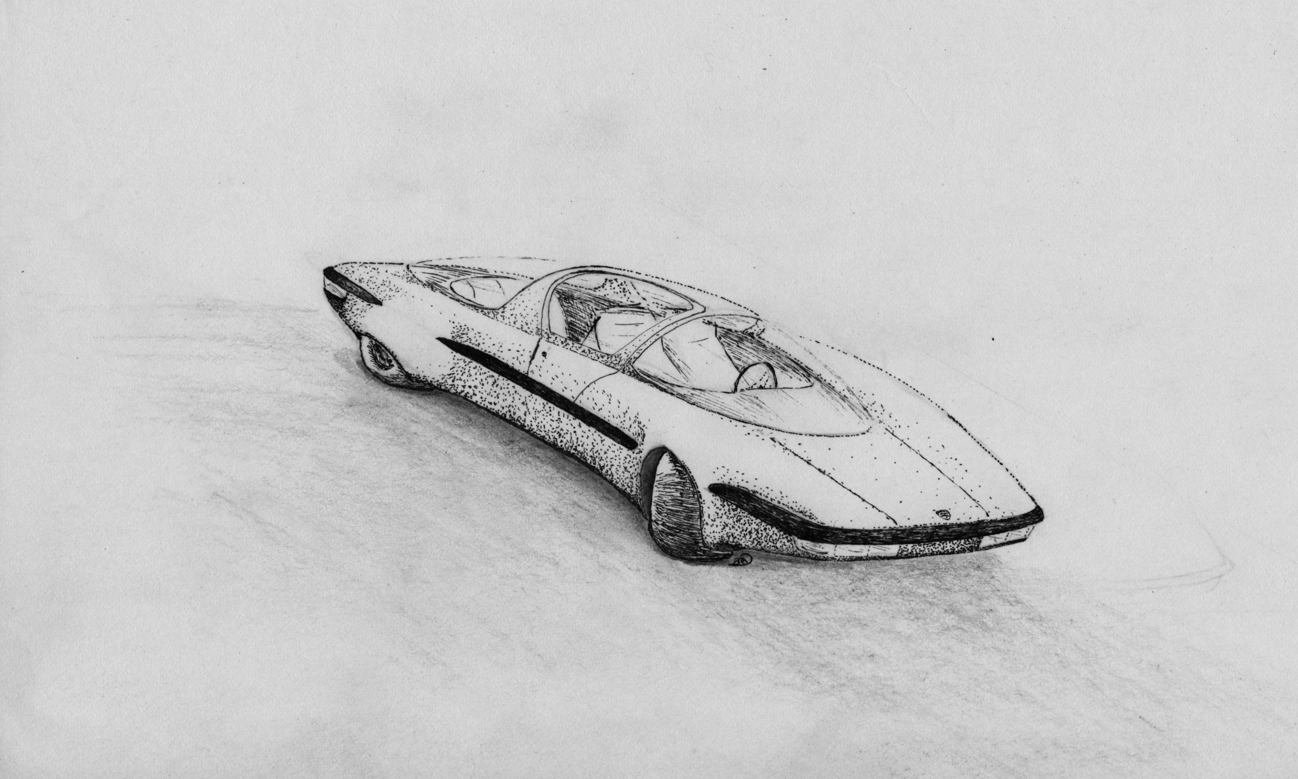
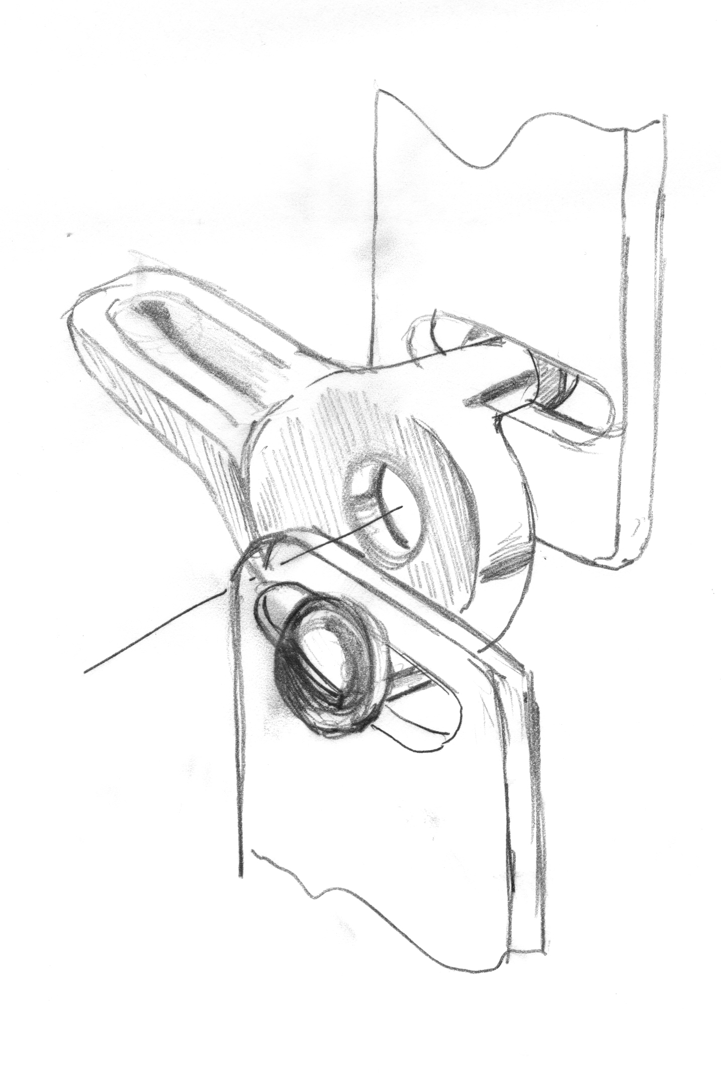
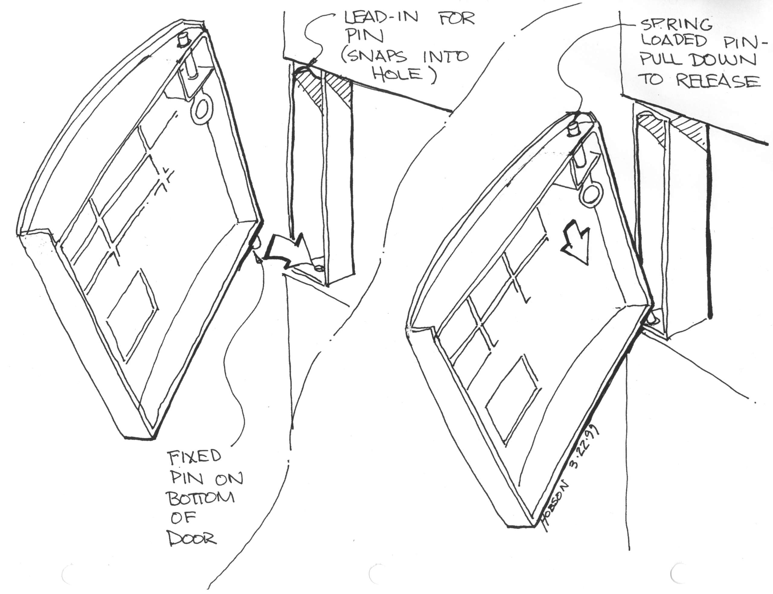
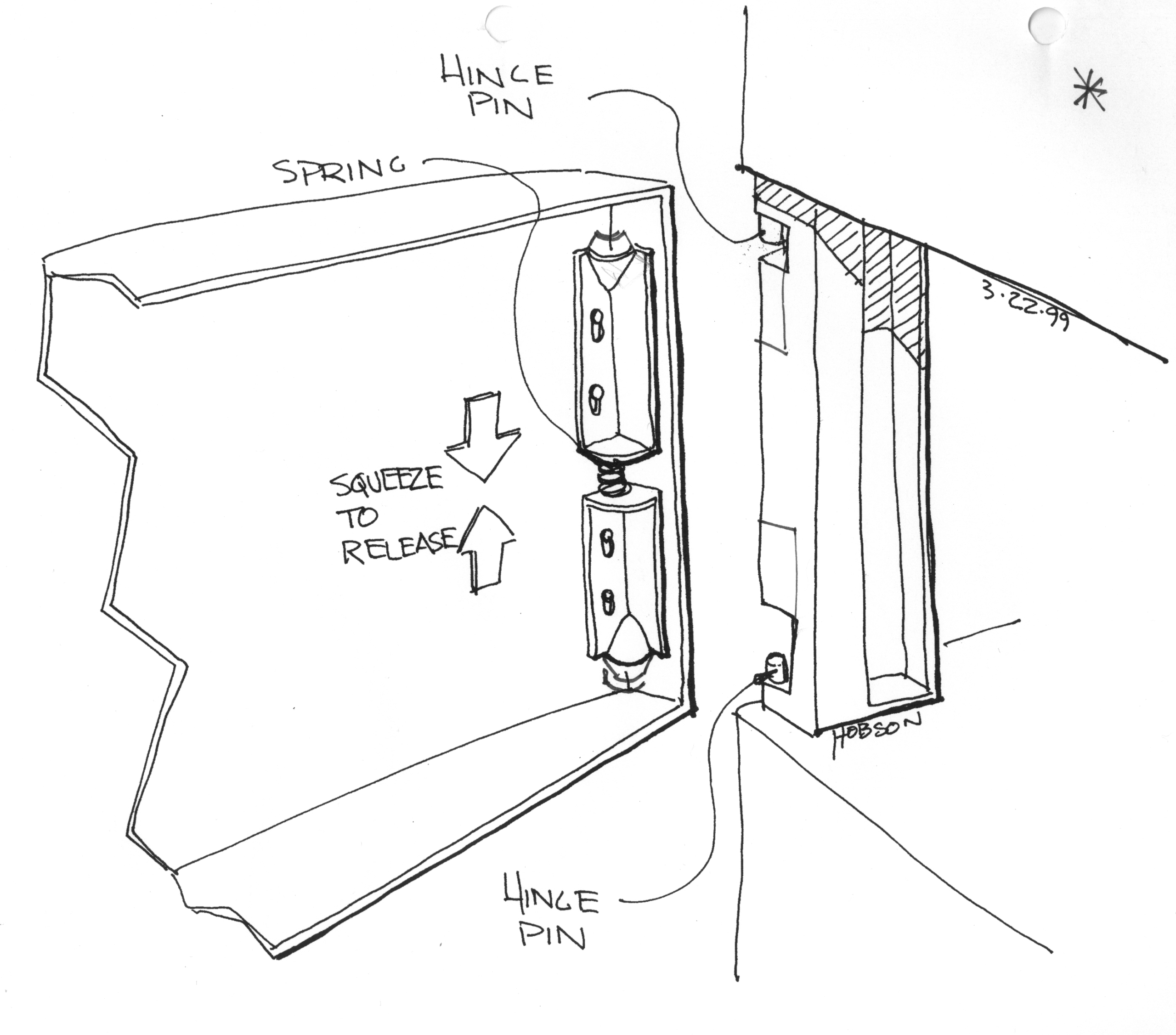
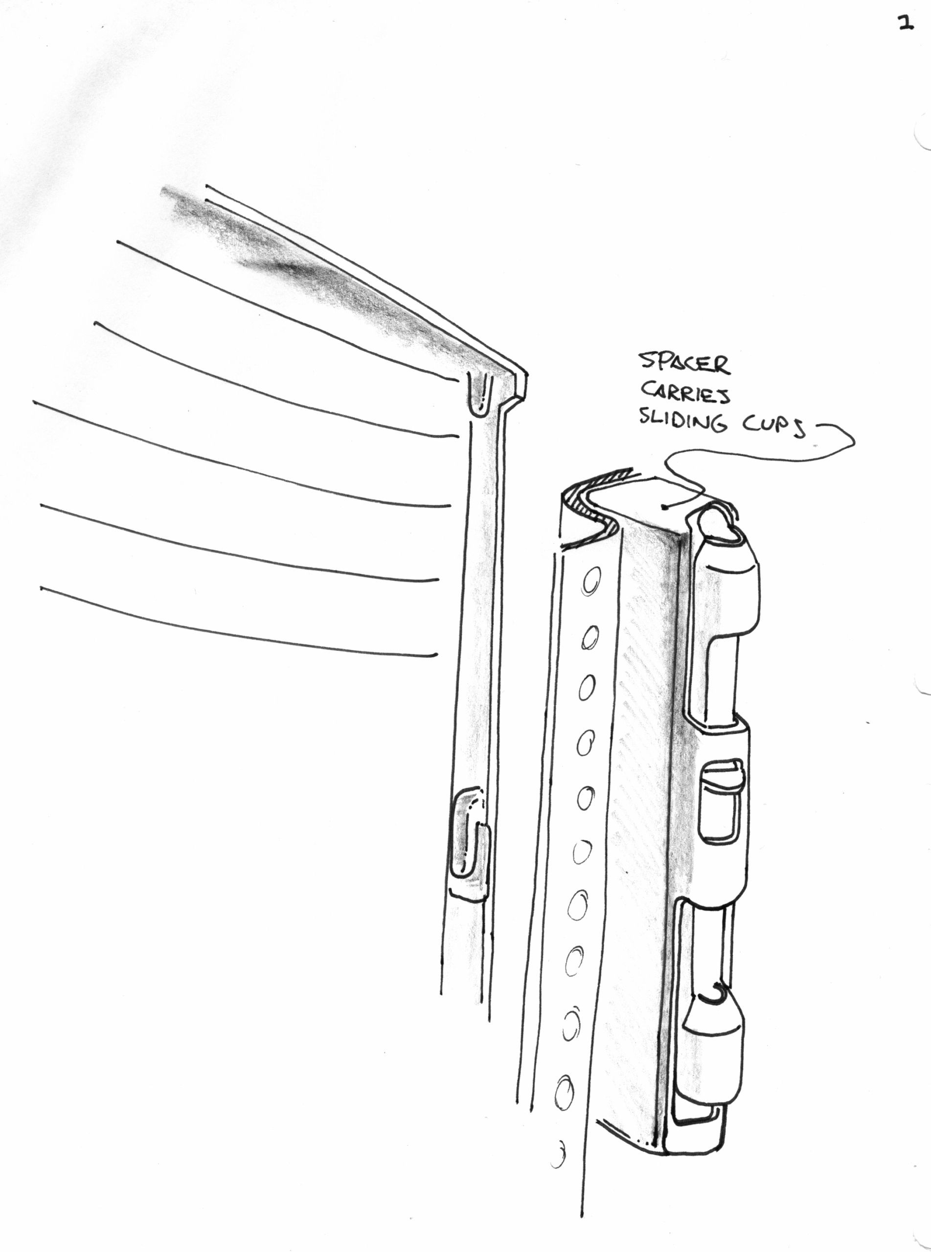
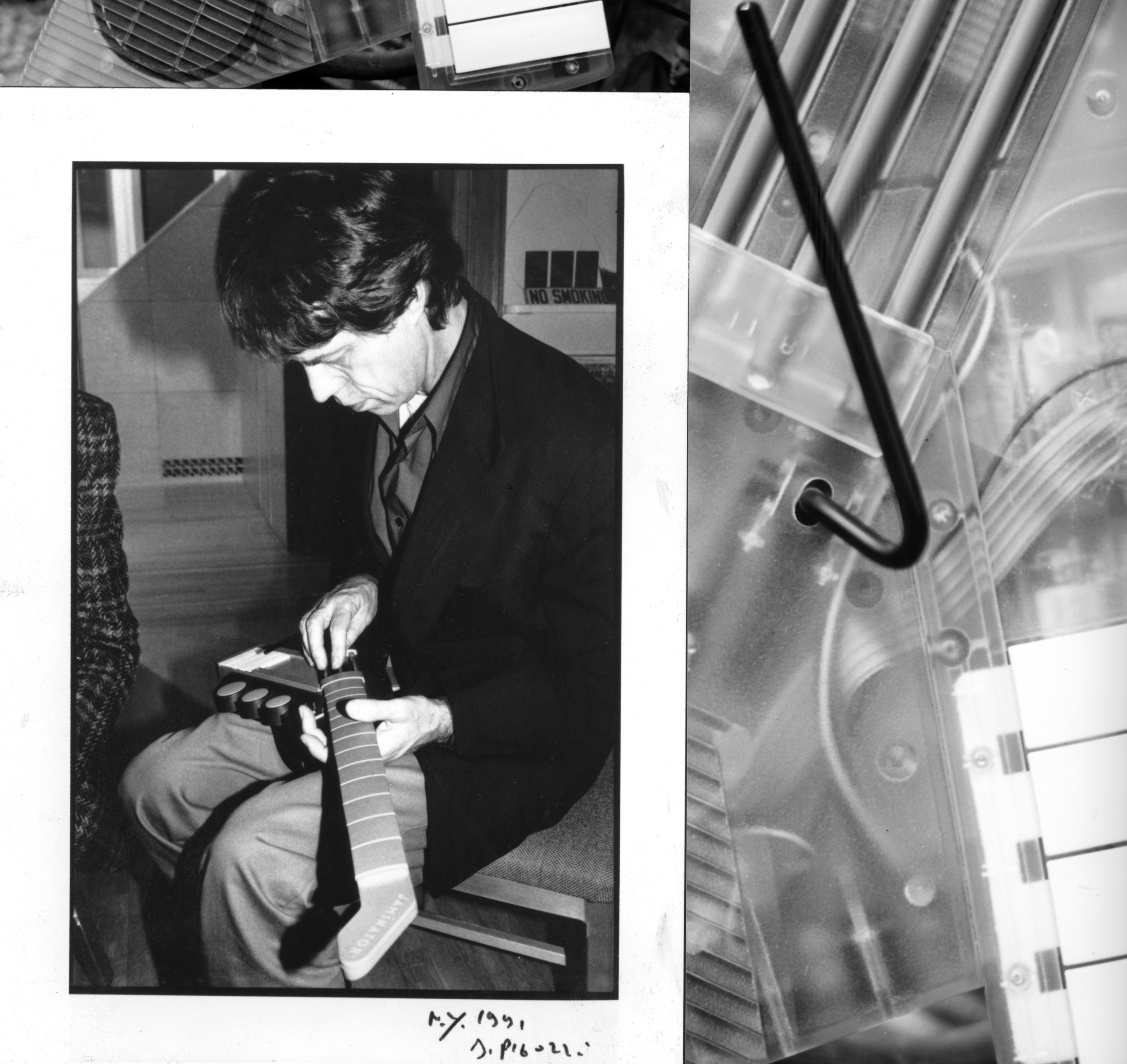
I’ve been practicing physical product design for a while. I studied drafting (with a T-Square, triangles, circle guides, drafting dots, a mechanical pencil pointer, powered erasers, and erasing shield) in high school and pursued a mechanical engineering and product design degree in college because I loved both fine arts and the sciences. At the time, I didn’t realize how different art-based problem solving can be from design or engineering-based problem solving. I thought it a bit odd that my favorite design professor accused me of “being an artist, not a designer” before giving me a good grade in his class. It took me a while to get what he meant. Perhaps you’ll start to get an idea from drawings and “designs” I was doing at the time…


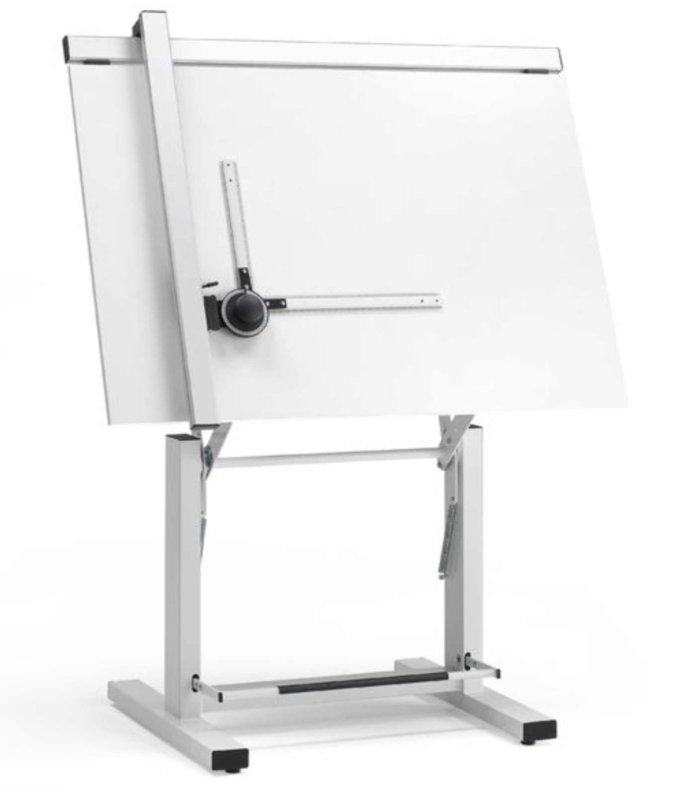
I secured my degree without the help of computers or the internet. My graduation present was a Mutoh, left-handed ‘drafting machine’ mounted on a Bieffe, mechanically height & angle adjustable drafting table (like the table image below). I was ecstatic!
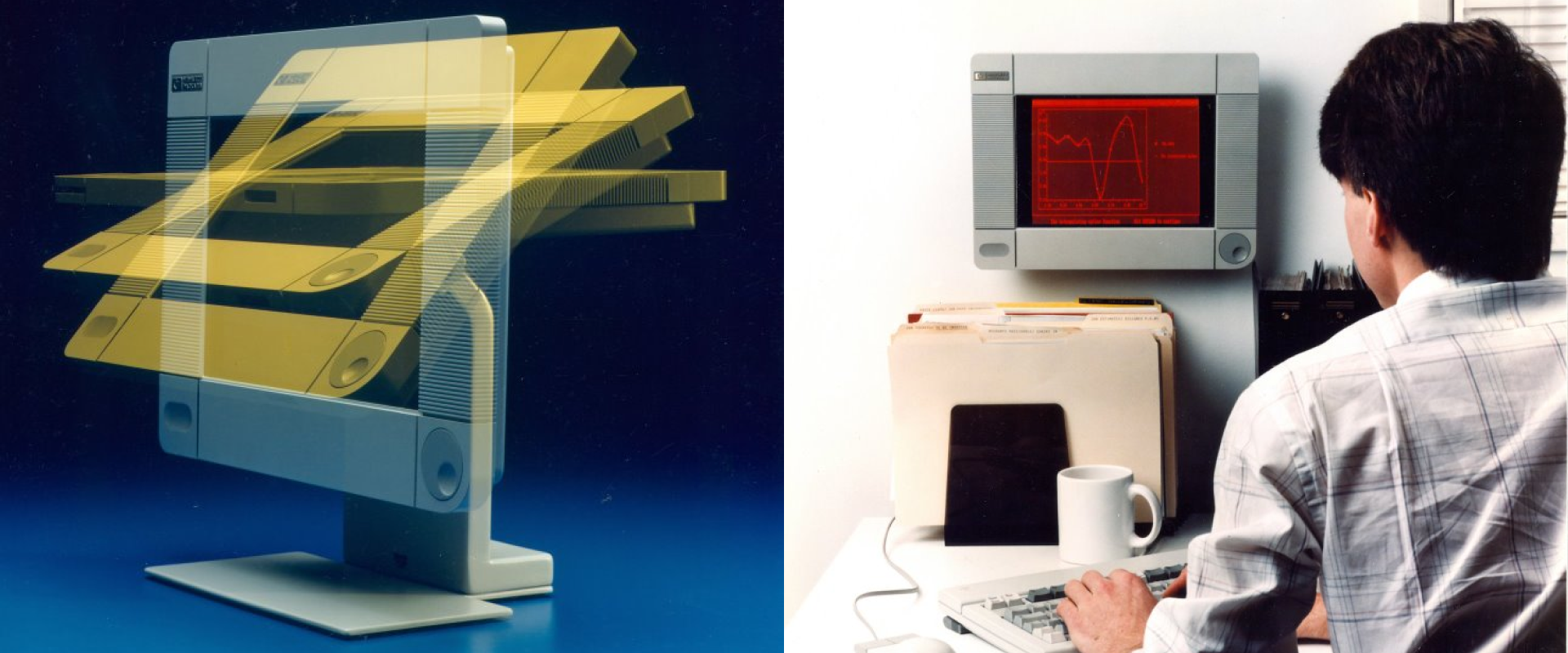
I started my career at Hewlett Packard in the early eighties as both a Mechanical Engineer (ME) and Industrial Designer (ID). I’d been taught in college that the best designers and engineers could wear both hats concurrently and I definitely wanted to, despite the fact that HP and most of the product development community insisted on keeping the disciplines separate. By historical sheer luck, I started my career at the dawn of mechanical engineering computer aided design (CAD).

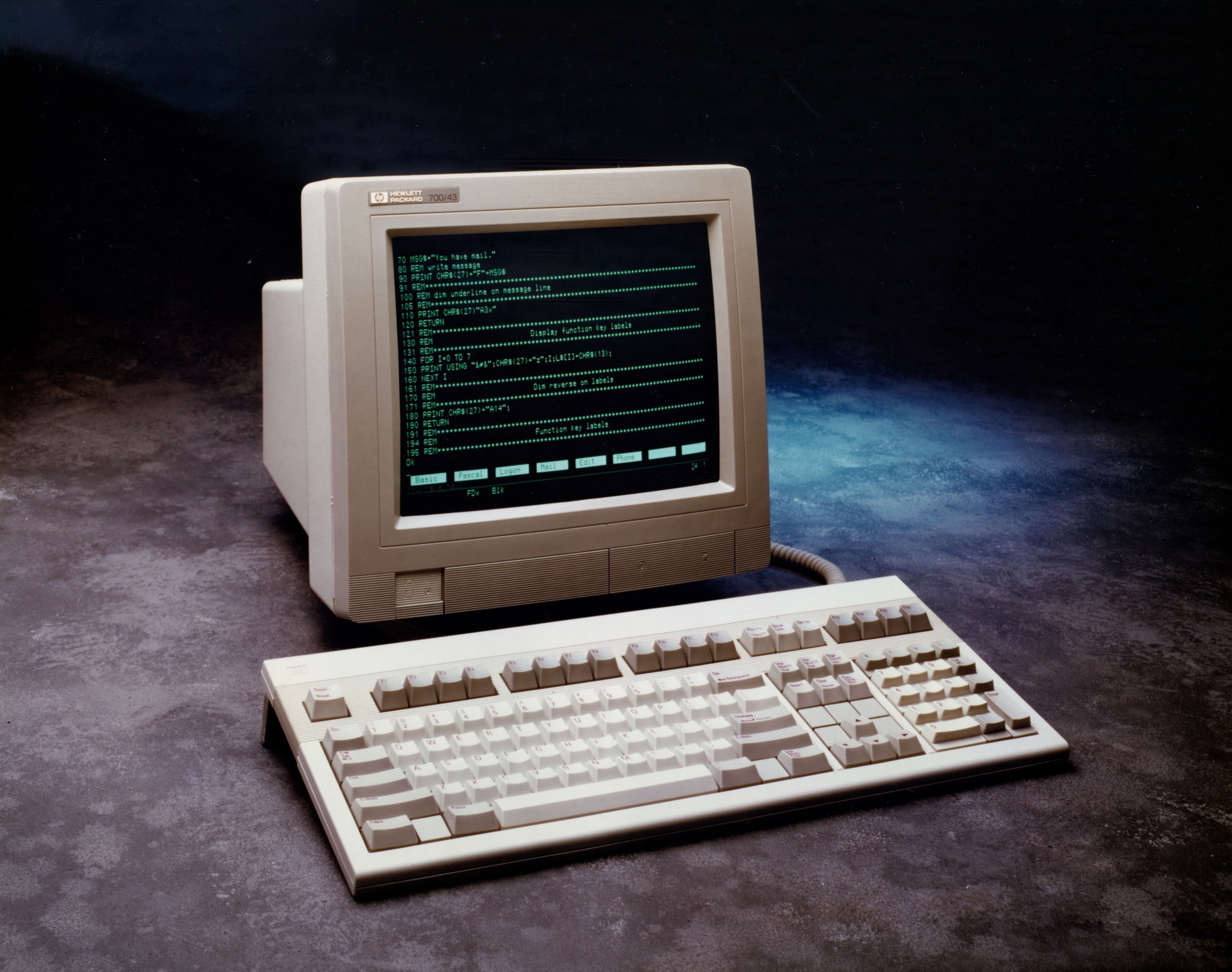
At the Roseville Terminals Division, near Sacramento, CA, I volunteered to learn “Piglet” aka ME10, a modified 2D printed circuit board (PCB) layout tool running on HP Unix workstations. I used it along with HP’s up-to-E-size pen plotter “Big Bertha,” to create sheets and sheets of fully dimensioned, detailed 2D mechanical part drawings of our designs.
Communicating design intent
The mechanical relationships between mating parts or components resided primarily in our heads, in foamcore mockups, and often a bunch of hand sketches.

The drawing packages that I’d blueprint in the wee hours would be released to tool designers, tool builders, and molding houses. These drawings and the tolerances on each dimension were mostly all we had to communicate our engineering design thinking.
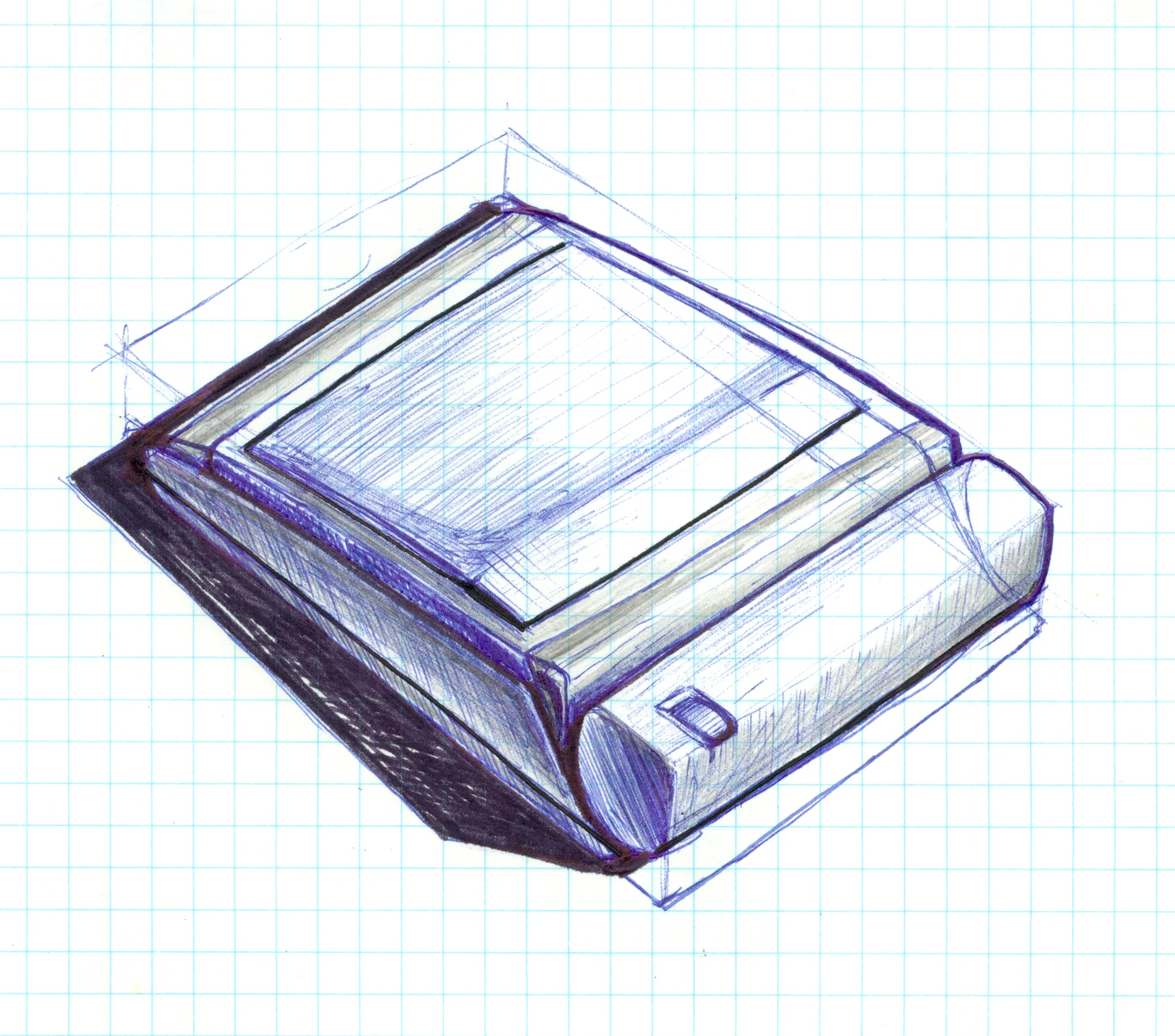
ME10 led to ME30, an actual 3D solids modeling system. Things got way more interesting: ME30 was like sculpting on screen and with super-fine precision. The renderings looked so real, so cool…even when the geometries blew up! At that time some prescient engineers theorized we could get away from fully dimensioned drawing sets. Just releasing 3D translations of our parts in universally readable formats. I could hardly wait.


Non-associative CAD vs. associative systems: history-based or no history?
I left Hewlett Packard in the early nineties to join David Kelley Design (aka DKD – originally Hovey Kelley Design, which would become IDEO five years later) in Palo Alto, CA. While HP had agreed to my working both ID and ME tasks, they almost never let me do them concurrently on the same project. David Kelley was among my college profs who’d sold me on the idea that the best design engineers could wear both hats. So I figured I might find more traction filling both rolls at DKD.
By then a philosophical conflict between associative (history-based) and non-associative (direct or wysiwyg) CAD modeling was well underway. Associative modeling captured every step you took in designing a part. Every time you loaded your file, the system would rebuild it, just the way you’d built it originally. While associative systems (like Pro/Engineer, now CREO) didn’t have undo commands (they do now), they did allow you to adjust variables, dimensions and sketches associated with each feature you’d built into the part. Non-associative solids modelers, like ME30, did have an undo command but didn’t record the steps you took in the file you saved. The undo’s were gone when you loaded a fresh session and there was never a way to adjust input variables after the command had been implemented (at least not in the beginning and not easily). When you loaded a file—a part or collection of parts, you were merely loading a list of surfaces bounded by edges connected at vertices, that, most of the time, were ‘watertight’ solids. ‘Watertight’ just meant that the collection of surfaces were continuous properly trimmed at the bounding edges which met at true intersections – everything properly connected all around without gaps. These files were, like the universal translation formats mentioned above, featureless (single featured actually): that is, their detailed geometry was communicated without any relationships or intent—what you saw was ALL that you got.
I came to DKD armed with the ‘HP Way’ (basically their engineering culture, values, rules and credos) and with a true non-associative CAD bias. I arrived with SolidDesigner, (HP’s new product brand name for ME 30), guru level skills. Through chance, hard work and not knowing better, I’d become a non-associative CAD modeling evangelist.
My thinking went like this:
Associative CAD systems have complicated deeply nested interfaces. They force you to know the answer before you’ve even started. They aren’t conducive to quick iteration. They’re constantly failing to regenerate (aka rebuild). They’re not flexible. They require so much planning that doing a bunch of what-ifs is painfully slow.
The idea of capturing design intent (which history was supposed to provide) was tantalizing, but in practice it was always easier and faster to just get the design done directly. If I needed to make modifications I could make them quickly in a non-associative system, because I intuitively understood the commands and how the application would handle my edits. I could always pull, push or delete faces or sets of faces to simplify and get the results I needed. I could hack (aka machine) or fill (aka extrude), unite or subtract (boolean solids commands), my way to the desired results. It didn’t matter how many steps I took to get there, because there was no history. If a part checked out as clean it was done. No failed features up the tree to re-figure out. No lack of ‘stickiness’ of point clicks or consistency of regeneration (rebuilds) on different machines.
Physical product design balancing act 2: history vs. no history CAD
Regarding physical product design balancing act 2 (history based vs. no history), I was saying that especially at the outset of a project, we need to move quickly and iterate on as many ideas as we can in order to pick the best approach. We should use non-associative applications because it’s so much easier to improvise and iterate with them. One idea leads to another. Non-associative systems enable you to throw anything down, react to it and move on from there.
Physical product design balancing act 3: fluid design vs. planning it out
Regarding physical product design balancing act 3 (fluid design vs. planning it out), I was a strong advocate for fluid – spontaneous and then pivot if necessary, design. I was rationalizing. These concepts do have merit, but thirty years later, I have to admit that this was the artist in me talking; the lazy, enthused, obsessed artist, who didn’t want to learn a new system; who wanted to realize his vision as quickly as possible, hopefully appealing to clients who wanted great design ASAP.
Non-Associative CAD systems don’t capture design intent nor relationships between parts or surfaces. I could make changes pretty quickly, even when they were as extreme as changing overall wall thickness. But only because I’d learned over the years how to “trick” the system into bending to my will. The knowledge was intuitive and based on years of dealing with CAD quirks.
More so now than then, we can be pretty fluid in an associative CAD environment. Especially if we open our minds a bit to process: If we hold back from starting right in with assemblies in SolidWorks; opting instead for single part files with multiple bodies representing different components or parts, we can keep all references internal and iterate quickly.
Thirty years ago, I wasn’t capturing intent using a non-associative, intuitive but powerful CAD system. There were a bunch of us HP and ex-HP employees rooting for SolidDesigner née CoCreate One Space née Creo Elements Direct (after PTC acquired CoCreate) to succeed and dominate the industry; or at least stay relevant in the CAD world. It didn’t.
I found ways to pull off successful projects using a non-history-based system, more or less, until about 7 years ago partly because, with regard to that first balancing act 1 – DIY & Release vs. Methodic, Documented Team Work … Well, I bet you can guess where I tended to land on that one!
We’ll get to that in the next post.