Article
Master Modeling Techniques, Continued: Keeping the Design Fluid and the CAD Flexible

May 14, 2026 ...

This is chapter 2 of our master modeling techniques blog series for SolidWorks CAD. To keep you engaged, we’ve broken it into three installments, which we’ll release over the coming weeks. I’ll reference files from the Pack and Go, “01025-800-0005653 – THREAD WARP TOP LEVEL ASSEMBLY_REV02V19.zip” which you can download, inspect, and edit as desired.
I work on these blogs between billable and internal projects. Since my last post, I’ve worked CAD on a medical device (that I’m really excited about), component fixture part design, internal wall layout, and weldment plans for a forty-foot shipping container that houses not-to-be-described systems, a remote video production product concept, and an autonomous mobile robot, (AMR).
I learn new lessons with each effort, and my opinions are refined by new experiences. Before we go back to master modeling techniques, let me share a couple new thoughts:
How master modeling techniques compare with emerging Solidworks workflows
#1: Virtual parts modeling in assemblies
I’ve seen a lot of virtual-parts-in-assembly work recently (some people call it “virtual assembly” modeling, although that can mean many things, especially outside the context of Solidworks). It does easily and intuitively, some of what I try to achieve with master modeling:
- All of your design can reside in a single file holding all its data and references.
- It enables holistic, fast fluid design – you can add components on the fly, as needed, while working in a familiar SolidWorks assembly format.
- When you insert a “new part” into an assembly, the default top, front, and right datum planes of the new part are coincident with the top, front, and right datum planes of the assembly, meaning that, as with master modeling, you won’t need to mate up your part at a later date. Of course, you might need to “fix” them, but at least they start out in the right places.
More advantages of virtual (parts-in-) assembly modeling
Virtual assembly modeling allows you to mix external parts (independently stored files inserted as components) with components created “virtually” in the assembly. The virtual parts are only stored with the assembly, similar to bodies in a part file. You can literally start with one file, inserting off-the-shelf components and designing custom parts virtually, in the context of the assembly, as you think of them. You can convert any of the virtual parts to external parts at any time… Or never.
When you convert virtual parts to external parts, their features, defining sketches, and references go with them, so they can still be edited. If features referencing other assembly component geometry were created before the part was externalized, then edits to those references should ripple through the part even after you save it externally, and conversely, if that part was referenced by other parts features, then those features should update as well. Of course, references to and from features outside of the part are external, all the more so, when the part is saved outside its parent assembly.
Virtual parts modeling in assemblies is friendlier than master modeling. Virtual parts modeling doesn’t require advance planning, helping you to avoid hesitation anxiety – asking yourself questions like:
- “What should I do next?”
- “What should I include in my master model?”
- “Where in the sequence should I build this feature?”
- “What references should I work from for this feature?”
It’s a bit like master modeling, as long as you wait to save your parts externally.
Virtual parts in assemblies modeling appeals to designers who really want to start with an assembly. The process is especially appropriate when working with complex assemblies of mostly off-the-shelf components and relatively few custom parts. It’s also a great way for industrial designers to model up concepts to pass on to engineering.
Disadvantages of virtual (parts-in-) assembly modeling
Virtual-parts-in-assembly modeling won’t be practical for:
- bigger projects with coordinated design teams,
- lines of products using highly derivative design forms or language, or
- products made of a bunch of interrelated custom parts or zones – where even small geometry changes in one part of a layout ripple through other parts and features.
For these you’ll still benefit from some level of master modeling. Without a master model or two, it will be more difficult to resolve last minute design changes that affect multiple externalized parts of your design.
Once you’ve saved out a virtual part there’s no going back: If you haven’t already defined the relationship between parts, i.e. design reveal gaps between parts, etc. you’ll effectively have to model them twice or at least edit in context in your assembly, creating external references that may get tangled (circular referencing) or otherwise slow you down later.
The biggest disadvantage of virtual assembly work is that only one person can work on the assembly at a time. Imagine that you’ve launched into a top-level assembly (TLA) and, for convenience, you’ve inserted all the anticipated custom parts virtually. If you’re on a team and you’re not ready to save those parts externally, no one can work on them if you have the assembly checked out. I suspect that virtual assemblies are so popular with ID folks because they often work and iterate solo on designs, copying entire assemblies and assigning new version or revision numbers, or new filenames, to alternative solutions.
#2: Different types of master modeling techniques and when to use them
The ThreadWarp master modeling technique I share below is one I’ve used successfully while working solo and with ME teams on consumer and medical electronics enclosure products. It involves defining the core ID as surface or solid bodies, adding relevant internal fastening zones and other important datums in the form of sketches, planes, axes, 3D points or simple volumetric bodies, and then inserting the master model as the first feature of all subsequent detailed part designs.
With ThreadWarp I take it a step further by creating an ID master model 1 (MM1) first and then inserting MM1 as the first feature of master model 2 (MM2). MM2 is then inserted as the first part/feature of the team’s detailed custom part designs. I attempt to put most or all of the internal mechanical and general parts architecture information in MM2, while keeping it as simple and concise as possible (for my teammates’ sake).
There are different degrees of and other ways to do master modeling that are effective and appropriate, depending on project type. In the communities I work with, debate continues about whether master model use is always appropriate…or even appropriate at all in some cases.
I mentioned a converted 40’ shipping container project above. Our team inherited many reference assemblies of previous designs from our client, including an assembly of the container we’d be redesigning, gutting, and retrofitting. The files submitted were assembly files without master models and were full of off-the-shelf hardware.
While I did do some multibody part modeling for custom subassemblies that would eventually be split out as individual parts, we never built a master model. Given the starting point, the project wouldn’t have benefited from it. Our client wouldn’t have appreciated our taking the time to build one.
This is an issue often faced by consultancies. Master modeling techniques can save significant time if scope or design requirements change downstream. If we had started from scratch on their project, knowing in advance that we might need to make similar solutions in 20’, 40’, and 53’ containers, maybe a master model that could be copied, versioned, and dimensionally modified for each version would have made sense. But for a consultancy doing a one-off project, with the client expectation that we’d leverage as much of the previous CAD as we could, building a master model for the whole layout didn’t make sense.
Many of our one-off automation projects have worked out fine without master modeling. If an automation or large scale complex project can benefit from a master model—one that identifies a general layout of a production line perhaps, with a few sketches, some important datum planes or axes, fastening/anchoring points etc.—it certainly wouldn’t follow the process I share for ThreadWarp:
We wouldn’t insert the master model as the first feature of every custom part of the system. We’d just include it as an inserted component of the top-level assembly and ask team members to reference it “in-context” in the development of subsystems.
Master modeling comes into its own if the designer plans to leverage the MM across multiple versions of the same design, perhaps in different sizes that can’t be handled well with configurations. It can also save considerable time if the design is volatile – if the designer anticipates some unknowable, even subtle but significant, late change(s) to the design.
Before I joined our internal project, FreshRoll, an autonomous mobile robot, we asked Senior Mechanical Engineer, Jordan Heintz, to develop a master model. As with ThreadWarp, he built two-part files, but we’d only call one of them a master model. He limited the information captured by the master model to basic vehicle layout geometry and sensor locations. He then inserted the MM into an ID-only part model.
Our Industrial Design team had given him an ID form model designed specifically for our small skid steer solution. He reverse-engineered it and built out the project ID model so that it references and is derived from the basic geometry and components placement defined in the MM. As we work on future, different sized, indoor and all-terrain models, we hope to leverage the ID language by adjusting global variables in the MM to drive new implementations of the ID and mechanicals.
Applying master modeling in a real-world robotics project
The following screen grab shows Jordan’s complete MM. Note that, unlike what I often do with consumer product design, there are no solid or surface bodies, just planes, axes, and simple sketches!

Jordan based all of his reference information on a set of global variables he defined in the “Equations” folder. His MM is easy to adjust and concise. Within limits, the ID and detailed internal part design will follow significant or subtle changes made to the global variables in the MM.
The following list of links may help you understand how to use global variables in your SolidWorks design work:
- SolidWorks Fundamentals: Global Variables (Beginner)
- How to Use Equations & Linked Variables (Beginner)
- Utilizing Equations to Automate Your Design (Intermediate)
- Utilizing Equations to Automate Your Design (Advanced and assembly and automation focused)
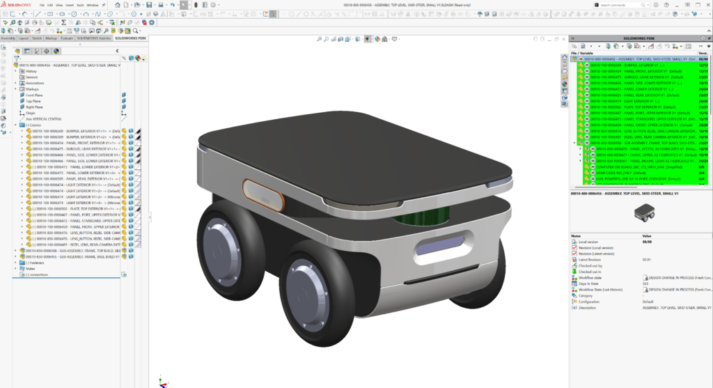
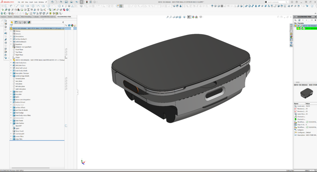
Here’s a screen grab of the top-level assembly of our finished small skid steer vehicle.
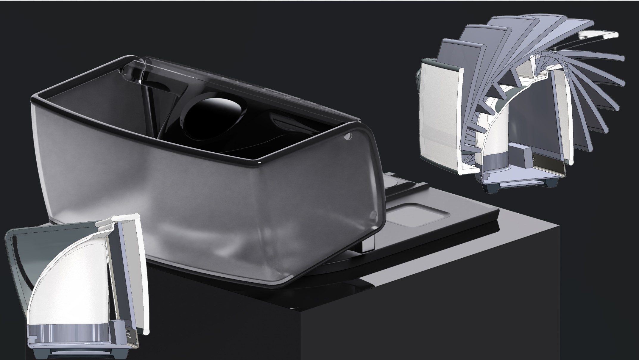
Jordan inserted his MM1 (as the first feature) into an ID-only model part file. The images below show nominal ID (exterior) and all of the mechanicals (internal and components layout) output with the global variables set to a small skid steer. I did all of the chassis and internal component work using only his MM1 for parts development references. Jordan’s ID definition is completely independent of my internal workings. But they both follow his MM1 to start.
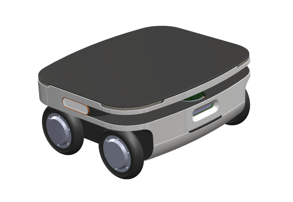
I was skeptical about this approach at the outset. But we needed to work fast to get the small skid steer released to our Fresh tech team to start the physical build. This approach enabled us to work in parallel. See Jordan’s completed ID (outer body parts) output followed by my released chassis work:


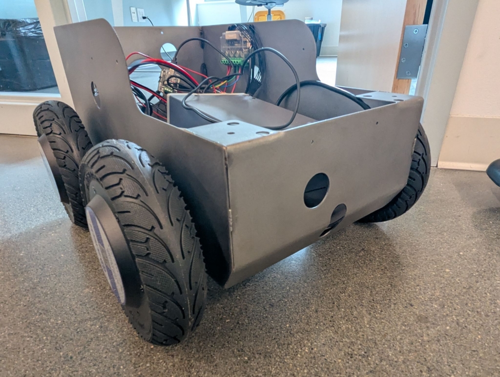
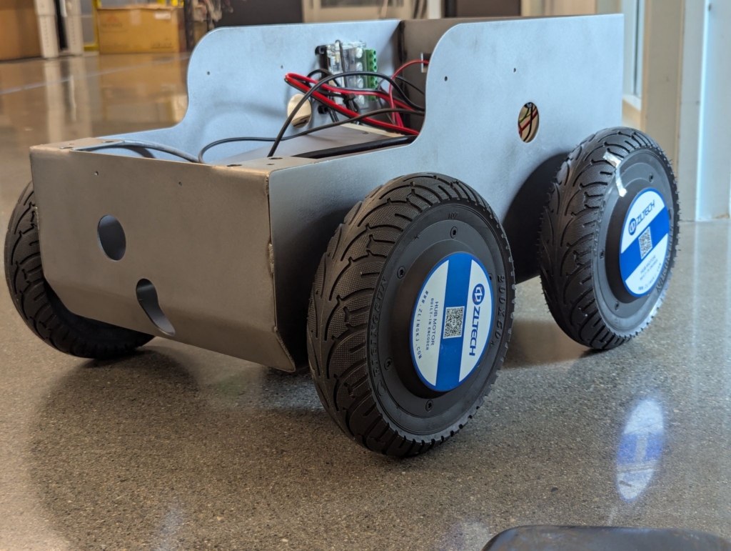
Both Jordan’s ID part file and my internals assembly file are inserted as components into the top-level assembly without need of mating and match perfectly! When we got to this point, I released our internal design CAD model along with limited fab and weldment documents to Elliott Stryjak, senior fabrication technician – one of Fresh’s hardware techs, manufacturing hardware engineers, and our most skilled welder.
Elliott took our design, built the outer most chassis, and passed it on to our Robotics team, who built it out as far as they needed for now. Keep in mind that Fresh teammates work on internal projects when there are lulls in our workloads. It made sense to take the design this far in fab and do a partial build-up.


Months later, I decided to test Jordan’s master model approach, imagining that Fresh had decided to implement the next vehicle. We’d want to tweak a few starting layout dimensions in the MM (to change size, wheel base, wheel clearance, wheel diameter, etc.) and then do minimal CAD re-work, using the same internal hardware, maintaining original design intent inside and out.
First, I did a Pack and Go of the released top-level Small Skid Steer assembly to my personal sandbox folder, clicking the option to append a “BSM_VEXP” to every filename so that there was no chance of confusion or overwriting our small skid steer work. Then I changed two dimensions by “managing” the equations in the table at the top of the feature tree in Jordan’s MM copy (which, of course, was included in the pack and go).
I specifically changed:
- “Wheel Base” (was 285mm; became 300mm) and
- “Track” (was 350mm; became 600mm)
The shape and overall width of the basic “sketch01-Wheels and Wheelbase” changed dramatically – I’d lengthened the vehicle by 15mm and widened it by 250mm:

The image below shows the subsequent rebuilt ID model with no cleaning or fixing by me. No features broke, and it’s super close to what we’d want to see, with only two unwanted steps created at the bottom where the toroidal swept “chin” surface is supposed to meet the vertical cylindrical surfaces at front and back tangentially.
It took me less than half an hour to find and fix the problem with the ID model. I redid a couple of tangency relations in two sketches of Cut-Sweep sketches that define the undercarriage details.
Features in subsequent parts often break when making gross changes to master models, but finding and fixing the breakages, while a bother, is straightforward and leads to more and more robust models. Often, small dimension adjustments don’t break at all.
Ideally, a robust top-level assembly of derived parts would handle even big changes from their deriving master model(s). The changes would just ripple through each affected part on the next full rebuild (because each part starts from the revised master model). But that only works if the part designers reference master model geometry appropriately.
In my case, the internals and chassis subassembly, I didn’t get those references quite right the first time. The next two screen grabs show the initial resulting top-level assembly after making tweaks to the global variables in the MM: corner LED strips are floating in space, and the wheels are inboard of the body—see the red arrows. Keep in mind that this screen grab was taken before I’d fixed the tangency problem at the chin and rear of Jordan’s ID model.
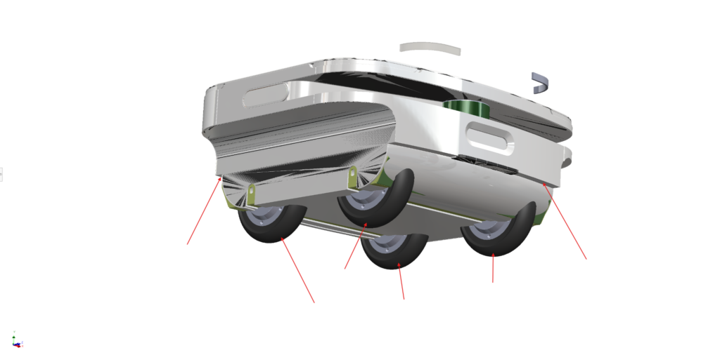
Several mates and a few features of parts in the chassis subassembly were breaking:

But, after less than half a day of work, I had a clean top-level assembly. I deleted the broken mates, updated a few sketches, reattached a few sketches to missing planes, updated some delete/keep body features, and redid a few fillets in individual parts. It may sound like a lot, but it wasn’t bad. And the new Wide Body Fresh Roll Skid Steer was born!


The ROI of master modeling techniques in iterative design
The original complete small skid steer project took a couple full time weeks to design and complete. Doing a “what if” on a wide-body design took me about a day, all in. All with the same internal hardware components in viable layouts. And without any significant participation from Jordan. That’s a huge time savings and convenience.
Now, with each iteration, our master models and top-level assemblies will ripple more effectively. We can attain big leverage, using master modeling techniques in the right settings! I’m glad Jordan insisted we keep the exterior ID part file (derived from the MM) independent of the internal assembly file work (also derived only from the MM).
I look forward to iterating again on Fresh Roll.