Article
Toy Story: Using Small Toys to Demonstrate Big Concepts

August 4, 2020 ...

Our clients had a problem: “How can we showcase our turnkey solution for autonomous solar site installations, some spanning over 120,000 square feet of land, in the relatively small space of a convention hall room?”
Our response was simple: “Miniaturize the solution.”
As consultants, it’s our job to provide simple solutions to hard problems, but simple solutions often have layers of complexity to them. This is the story of miniaturizing an autonomous solar site installation. A Toy Story.
ROC: A Proprietary Tool Powering Autonomous Vehicle Navigation
At life scale, the autonomous program included many components working together. Among these was ROC, or Robot Operational Control, our Global Path Finder software that powers the navigation of autonomous vehicles. In the case of solar site installations, the autonomous vehicles were Bobcat CTLs, or Compact Track Loaders. We needed a miniature CTL to represent a life-size Bobcat.
Meet our miniature CTL:
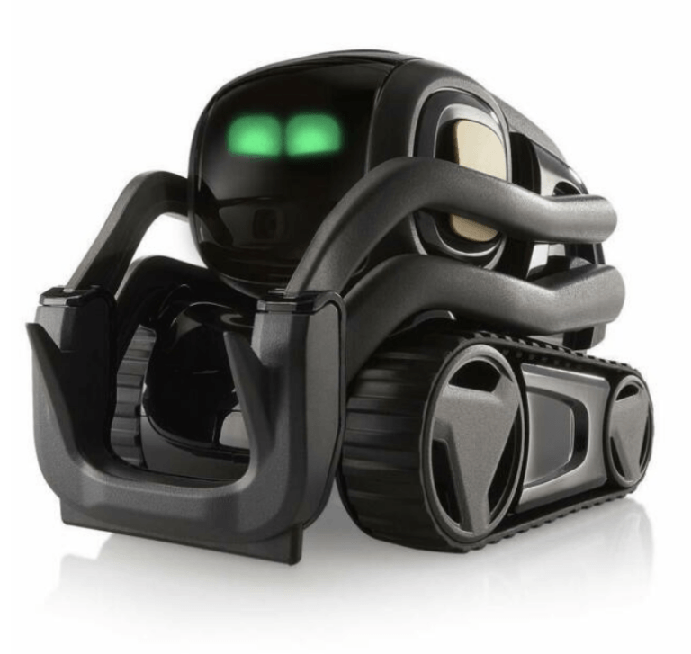
Anki Vector, a toy robotics company, had already created adorable little “Personal Companion” bots referred to as “Vector.” These toys could tell you the weather, give you a fist bump, and most importantly, were provided with a Software Development Kit (SDK) to customize our control of them.
To simulate our autonomous solar site installation, a customized Vector robot would use ROC to navigate over a “playmat” representing the solar site, and just like with the CTLs in production, the Vector’s position could be tracked in real-time.
Creating a playmat solar site
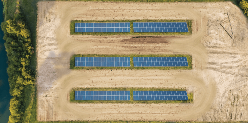
ROC works by interpreting real obstacles, defined by their geodesic coordinates, and outputting a path of waypoints that allow autonomous vehicles to navigate safely. On large solar site installations, measurements must take into account the curvature of the earth, because distances measured over a sphere-like object have different properties than distances measured over a flat surface. Because of this, ROC considers everything in Geodesic points, and we didn’t have time to alter its interpretation for a flat play-mat for the show. We would need to import the mat as though it were actual satellite imagery with real position data.
Enter, our satellite imagery:
When setting up a new solar job site, one of ROC’s first tasks is to determine where the site is located. To keep the math simple, we considered the lower-left of the toy mat as being at latitude/longitude point 0,0 — a geodesic position affectionately known as Null Island, where there’s nothing but ocean for miles. The goal for us was to overlay a digital image of our playmat at this position. So, if the lower-left corner is at 0,0 — how far east is the lower-right corner of the playmat? How far north is the upper part of the map?
If a real CTL is x meters in length, how does that compare with the length of a Vector toy? Using this as a guide, a scale was proposed.
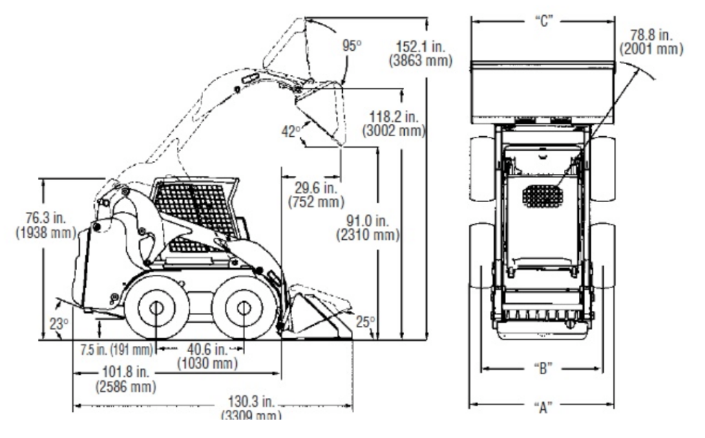
We used a scale of 1:35, so 1 centimeter of playmat would be 35 centimeters of satellite imagery. With that in mind, we measured our initial playmat and determined that it would be considered ~42.7 “real-world” meters wide. Then, we knew where the lower-right corner of the map would be in real-life: 42.7 meters east of Null Island. Applying the same technique for the height, we determined where the four corners of our playmat would be as satellite imagery.
The final steps included writing a script, applying the scaling factor, and creating a digital image input for the playmat. From this, we created a sequence of cut out “map tiles” that served as sections of the image, visible at varying degrees of zoom. ROC was now ready to treat our playmat as a real place.
Localizing the Robot
When it came to localizing the robot, several more questions arose:
- Given a series of latitude and longitude waypoints provided by ROC, how could we get Vector to go to the right place on the playmat?
- How would ROC know where Vector should be displayed on the satellite map? If we put Vector on the lower-left corner of the mat, ROC should show a Vehicle as being at 0,0. If we were to put Vector, say, 30 centimeters up from the lower-left as measured with a ruler, ROC should display the Vehicle as being 1.05 meters north of the lower-left as shown by the satellite imagery.
As part of the Anki’s included Software Development Kit, Vector could track its internal “odometry.” When you first set the robot down on a surface, it can remember how many millimeters it’s traveled relative to its original starting point.
For example, if we were to command Vector to drive 50 millimeters forward, turn 90 degrees clockwise, drive 60 millimeters, turn 90 degrees counterclockwise (now facing forward again), and drive 25 millimeters, Vector would report that it was 75 millimeters forward and 60 millimeters to the right of its starting position. Using our scale, we could translate this delta into “real-world” satellite imagery positioning.
At first, we started simple. We would place Vector directly on the lower-left corner of the mat (0,0) and translate its odometry into real-world satellite imagery positioning. ROC was now displaying Vector’s position in real-time. As we commanded Vector to move across the mat, the virtual vehicle representing Vector moved accordingly.
There was one problem. Starting Vector in the lower-left showed Vector as being in the grass, right on top of a Solar Panel! Not exactly a comforting thought for potential customers of this autonomous solution. We needed to get Vector to start at the beginning of a Mission. Also, a new requirement was added: like a real solar site, we had to have multiple Vehicles running at the same time.
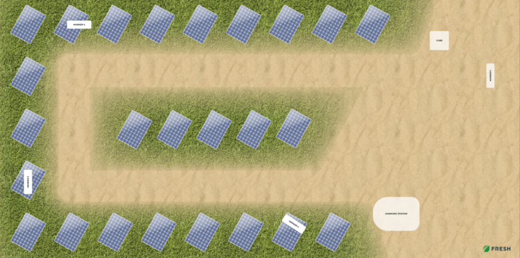
One of our UI/Visual Designers was brought onto the project, and a new mat was created. This one had enough space to do two missions at the same time, and would better illustrate the real value of this robotics use-case: delivering solar panels that were to be installed in rows.
Meanwhile, we worked together with other members of the Robotics Team at Fresh. Using a concept called Markers, we enabled Vector to figure out its initial positioning by looking at a specific image that we mapped to a real-world position.
Every time Vector’s camera viewed a Marker, it was programmed to recognize its position and orientation relative to that Marker. With that information, it could update its local odometry.
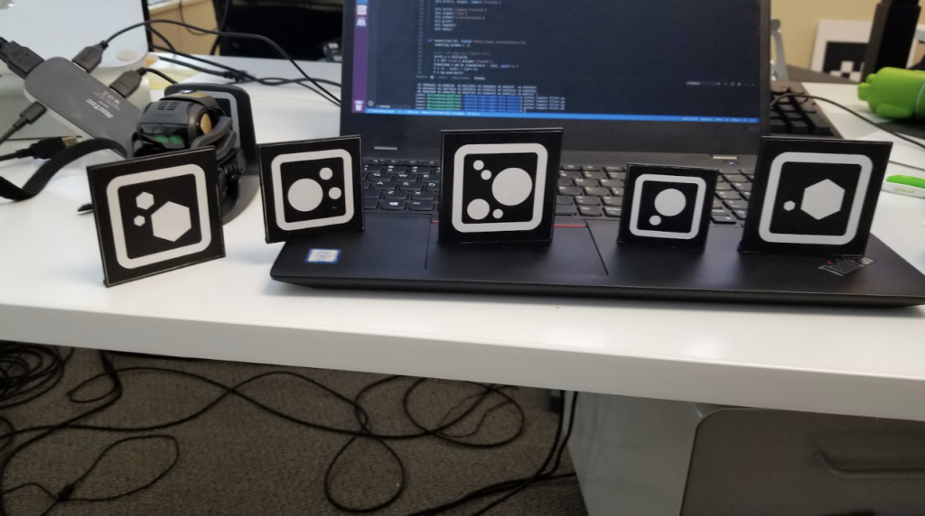
By placing these Markers at the “Mission Start” for each mission, we could place a Vector directly on the starting position and have it calibrate immediately off the Marker. Then, after each “lap,” Vector could calibrate again, which helped to account for the “drift” that robots can accumulate. Drift occurs based on factors like how slippery the surface a robot travels on is, or perhaps an obstacle that hadn’t been accounted for, which can cause a robot’s internal knowledge about its positioning to be slightly off from its actual positioning.
After completing these steps, we placed Vector immediately where it needed to start so that it could run lap-after-lap while staying on course, all while notifying ROC about its position in real-time.
The Orchestrator
On production solar sites, the CTLs were outfitted with a System Controller that would receive messages directly from ROC. The messages followed a Binary Protocol referred to as “cRIO,” and decoded cRIO messages might look something like “UploadWaypoints,” “StartMission,” or “StopMission.”
Vector, however, came with no understanding of these cRIO messages. If ROC was to give a command, there would need to be a way to translate the messages into commands Vector understood.
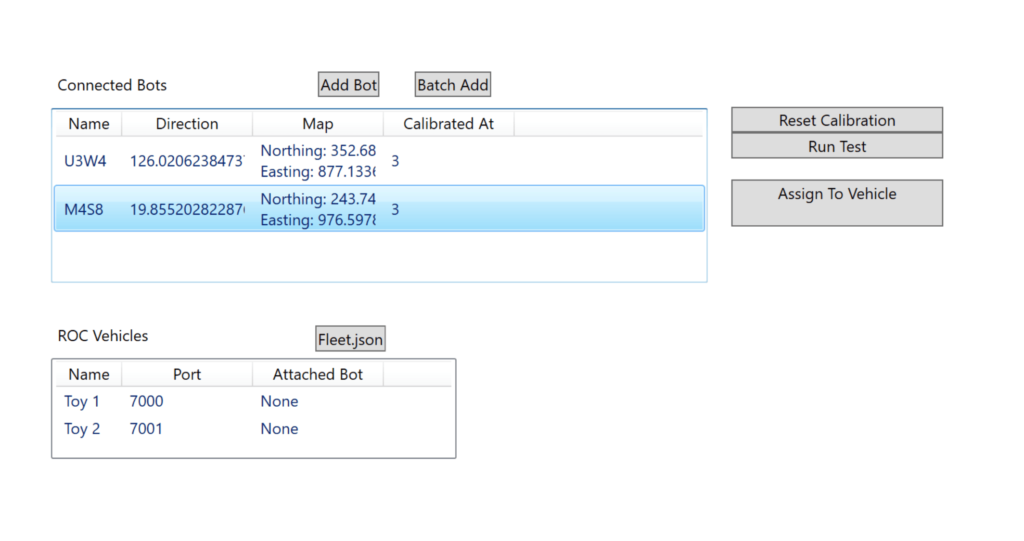
A Windows desktop application called the Orchestrator was made to allow for creating “Virtual CTLs” and associating them with the Vector. From ROC’s perspective, there was no difference between these Virtual CTLs and real ones. We programmed the Orchestrator to receive commands from ROC, translate them into commands known to Vector, send those commands to the associated Vector, and then send a message back to ROC.
This also allowed for a neat trick for a problem we were running into. We had approximately 20 Vector toys available to us. Each toy could only run for about 6 minutes before its battery dropped to a level where inaccuracies would build up egregiously. We knew that we would need to swap out toys mid-show at the conference, allowing the previously used toys to charge, and keeping the in-use ones within acceptable levels of accuracy.
Originally, for all 20 toys, there was a corresponding Vehicle known to ROC, and it could take some time for ROC to sync with a newly activated Vehicle. However, because each vehicle was actually a virtual representation of a real toy, we realized that ROC would only ever need to know about 2 Vehicles, which we dubbed T-1 and T-2.
The Orchestrator would allow us to change which toy T-1 and T-2 were referring to. So, once a toy, such as Vector-R094, was getting low on battery, we could put it on its charger, pick up Vector-S518, and tell the Orchestrator that T-1 now referred to Vector-S518. From ROC’s perspective, the Vehicle never changed, which greatly reduced the complexity of managing a fleet of vehicles within ROC.
Other Challenges
As mentioned, the toys had limited battery capacity. One of our Senior electrical engineers cracked one open to see how feasible replacing the battery would be with one of our own. However, this carried a risk: Anki was sadly going out of business (read more about it in our white paper, Why Robotics Companies Fail). Could we risk rendering our existing supply of Vectors useless, if no new Vectors were going to be manufactured and sold? Ultimately, it was decided that cracking open the rest of them was not something we could do so close to showtime.
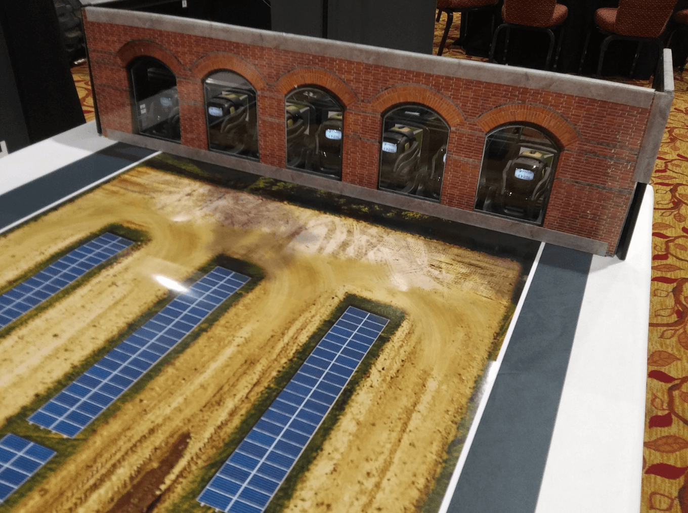
With a fleet of 20 toys, each with its own charger, cable management became a problem. It was also important to be able to quickly swap out toys as battery levels decreased. We needed a way to organize the toys in a way that would fit the story we were trying to tell. One of Fresh’s Industrial Designers teamed up with an Electronic Technician to do just that. Together, they created a two-level “firehouse” that served as Vector’s Parking Garage.
Another issue we encountered was that each Vector had its own little quirks. Some would slightly drift to one side or the other. Some would turn in jerkier motions, causing inaccuracies. Some seemed to be able to see the Markers well… others, not so much.
As such, the team spent time “characterizing” the toys. If each Vector consistently performed its quirk, we could compensate accordingly. We had some Vectors that were better at clockwise turns; these were to only perform the Top Mission. The Bottom Mission was reserved for Vectors that were better at completing counterclockwise turns. We had certain “stud” bots that were top performers. A list of each toy, along with which missions it was capable of doing, was compiled and packed.
The Big Show
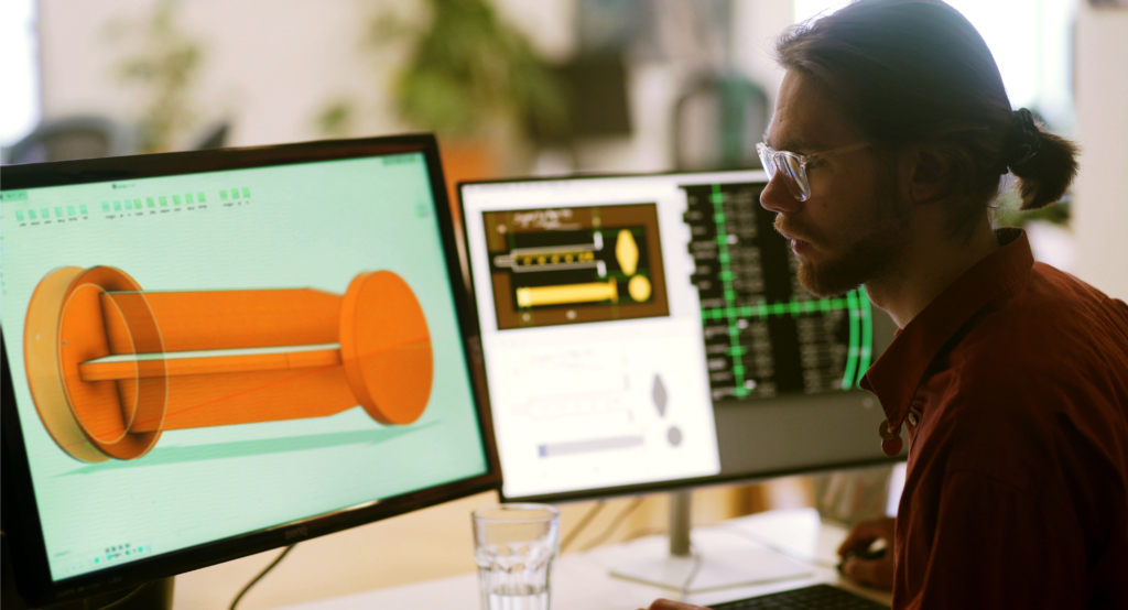
Six weeks after the development of the project had begun in earnest, the Total Control Conference took place in San Antonio, Texas, where I was flown out to run the demonstration. Meanwhile, James Dietrich, our Robotics Solutions Director sat alongside me and described the advantages of the autonomous program.
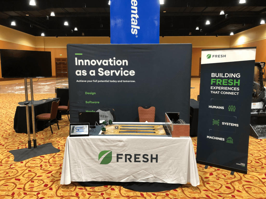
On the monitor to the left, ROC was running, showing the toys’ position in real-time while they moved across the mat, performing their job of delivering solar panels.
As the physical toys crept across the mat, groups gathered in front of the table. They watched as the Vectors performed their task. Via the monitor, spectators saw the path that had been planned for the Vector in ROC, and where the robot had already been from the “breadcrumb” trail ROC leaves behind vehicles as they complete their missions.
People noticed that an entire fleet of vehicles could be supported at a solar site. In fact, actual production solar sites have as many as 30 life-sized CTLs running at the same time! All the while, our visitors asked questions, learning more about how such an approach could help their business grow.
https://freshconsulting.wistia.com/medias/z8xpyfav73
After two days of being on the showroom floor, we felt good about what we’d accomplished. But questions remained: “Was our client satisfied? Were we able to effectively showcase what their autonomous program was capable of as they wanted?”
The client’s actions answered these questions. While only originally intended for this one conference, the whole demonstration was packed into their trailer so that they could continue to share their solution for autonomous solar site installations at other shows, showing that an effective story had been told.
A Toy Story.